Ammonia vapor management system and method

a technology of ammonia vapor and management system, which is applied in the direction of mechanical equipment, machines/engines, non-fuel substance addition to fuel, etc., can solve the problems of inefficient use of ammonia vapor in the exhaust, and achieve the effects of reducing residual nox, reducing nox, and reducing vapor pressur

Inactive Publication Date: 2008-09-18
FORD GLOBAL TECH LLC
View PDF35 Cites 34 Cited by
  • Summary
  • Abstract
  • Description
  • Claims
  • Application Information

AI Technical Summary

Benefits of technology

[0005]Thus, the reductant may be directed to various regions of the engine based on operating conditions. For example, at relatively high operation temperatures, ammonia may reduce a first amount of NOx in the combustion chamber and then reduce residual NOx in a downstream SCR catalyst. In another example, at low operation temperatures, ammonia may be used to recharge a urea or ammonia storage device to be later released into the system. In this way, it may be possible to reduce vapor pressures and reduce un-metered ammonia exiting the system. Further, by later use of the stor

Problems solved by technology

However, the inventors herein have recognized several issues with such a system.
For example, ammonia vapors may be used

Method used


Image

  • Ammonia vapor management system and method
  • Ammonia vapor management system and method
  • Ammonia vapor management system and method

Examples


Embodiment Construction

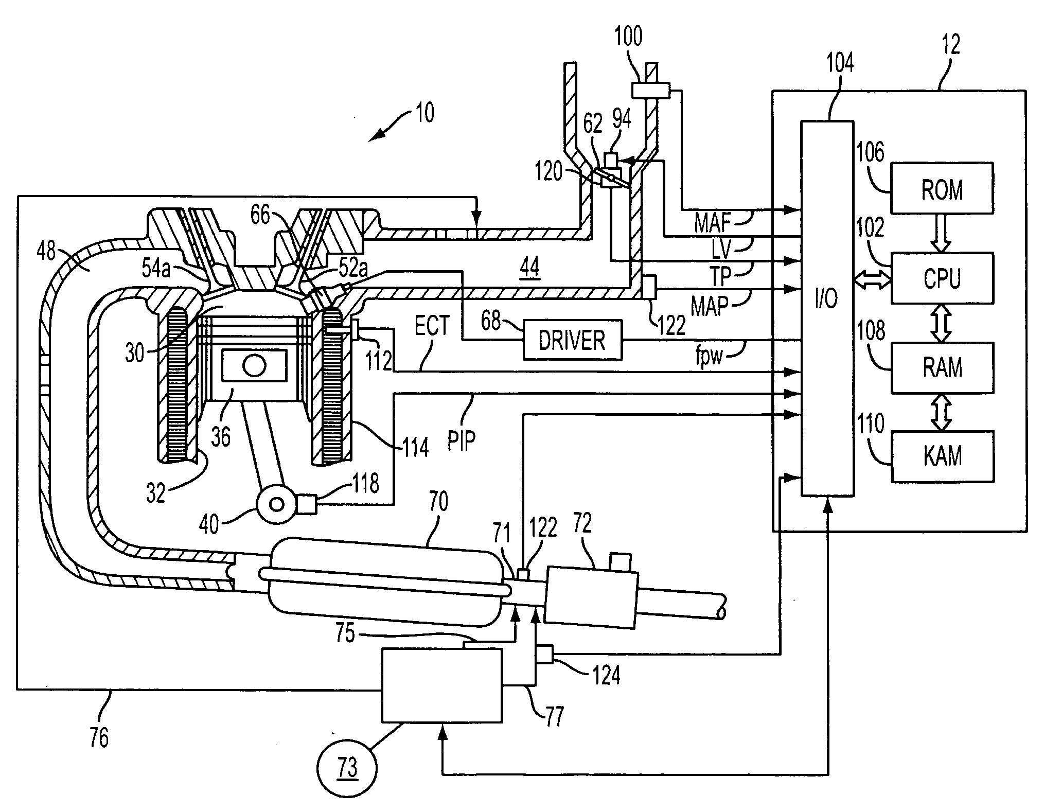
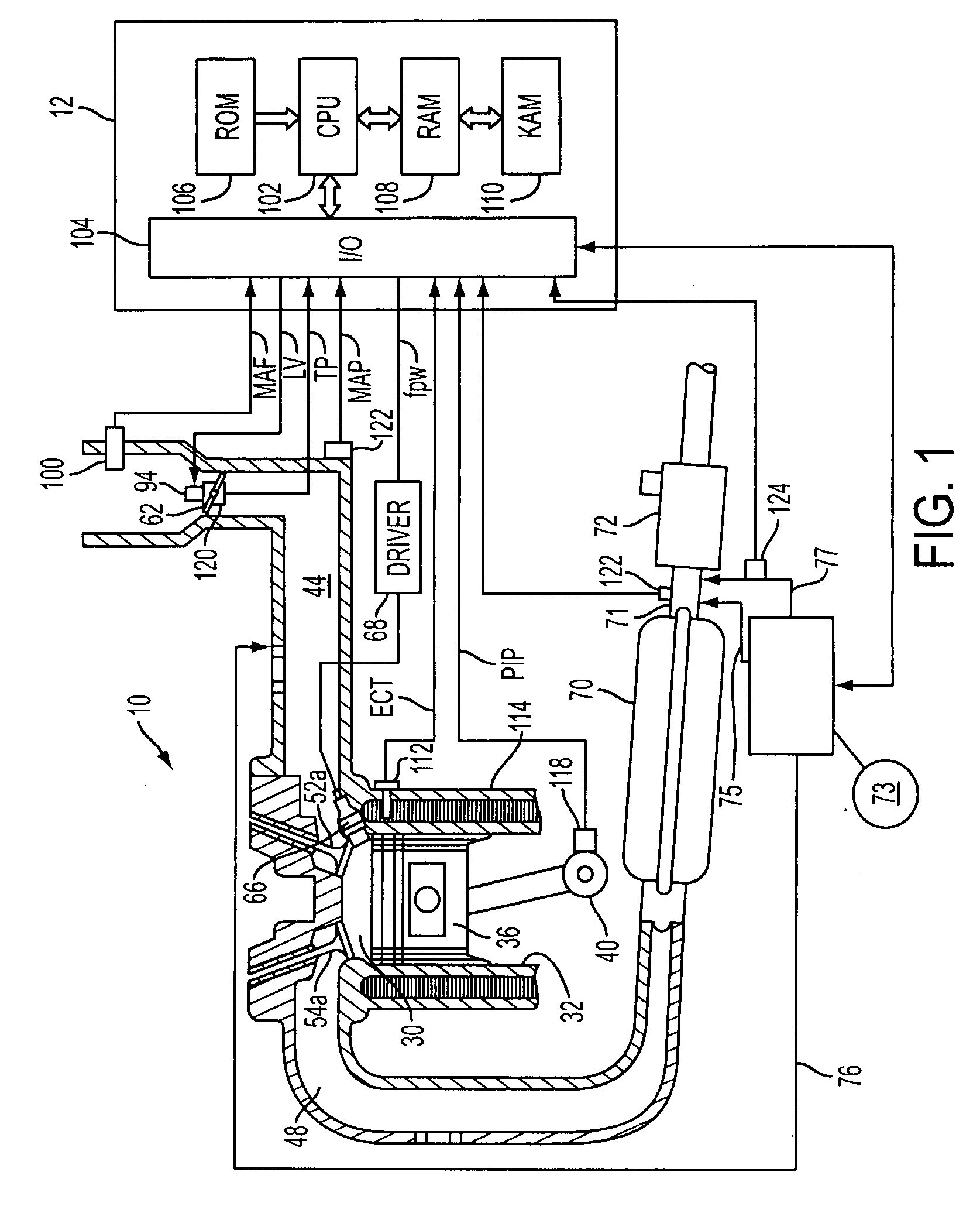
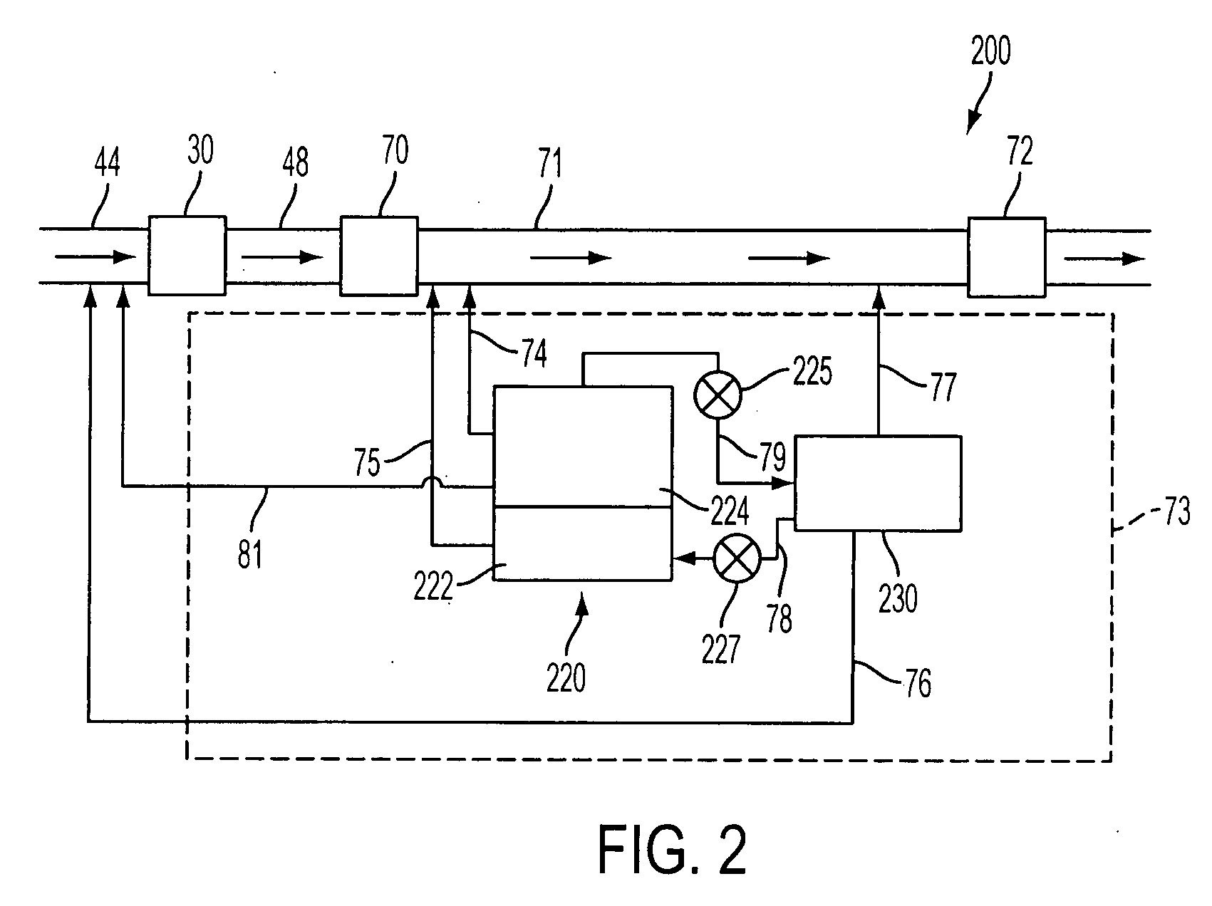
[0015]The accompanying figures and this description depict and describe various exemplary embodiments of a system for managing the storage and purging of evaporative emissions, such as with regard to an on-board ammonia or urea storage and metering system. Some of the embodiments described herein include a first storage device for storing the reductant, as well as a metering system to deliver the stored reductant to the exhaust system upstream of a catalyst for the reduction of various engine emissions. Further, a second storage device may be included for capturing evaporative emissions from the first storage device to reduce release of evaporative emissions to the atmosphere. Under selected conditions, the second storage device may require purging. The evaporative emissions stored in second storage device may be purged to the first storage device to be dissolved into first reductant or may be purged into the system. For example, the evaporative emissions may be introduced to an SCR...


PUM


Abstract

A method of managing vapors generated from an ammonia-containing reductant delivery system for an engine, comprising of storing an ammonia-containing fluid in a first storage device; generating ammonia vapors in the first storage device and storing said generated ammonia vapors in a second storage device; and purging said stored vapors from the second storage device to upstream of a combustion chamber of the engine during a first condition and downstream of the combustion chamber during a second condition.

Description

BACKGROUND AND SUMMARY[0001]Ammonia or urea may be stored on-board a vehicle for use as a reductant in exhaust emission control systems.[0002]Under some conditions, such as during ammonia or urea recharge, ammonia vapor that was generated in the reductant system may be used, such as described in U.S. Patent Publication No. 2006 / 0117741. For example, ammonia vapors may be routed to a storage unit and a reactor that uses catalytically generated heat from the exhaust or electrically generated heat. Further, the vapors may also be directed to the exhaust gas to react with exhaust gas NOx in a catalyst in the exhaust flow.[0003]However, the inventors herein have recognized several issues with such a system. For example, ammonia vapors may be used inefficiently in the exhaust, such as during various SCR (selective catalyst reduction) catalyst temperature conditions.[0004]Thus, in one approach, a method of managing vapors generated from an ammonia-containing reductant delivery system for a...

Claims


Application Information

Patent Timeline
IPC IPC(8): F01N3/10
CPCF01N3/2066F01N3/208F01N2610/02F01N2610/06F01N2610/10Y02T10/24F01N2610/1406F01N2900/12F01N2900/1811F02M25/14Y02T10/121F01N2610/14Y02A50/20Y02T10/12
Inventor SHAIKH, FURQANLAWRENCE, DONCOOPER, SCOTTCASTLEBERRY, LARRY
Owner FORD GLOBAL TECH LLC
Why Eureka
Try Eureka