
Heat exchanger

Inactive Publication Date: 2008-09-18
WHIRPOOL SA
View PDF3 Cites 9 Cited by
  • Summary
  • Abstract
  • Description
  • Claims
  • Application Information

AI Technical Summary

Benefits of technology

[0008]As a function of the inconveniences mentioned above and regarding the known constructive solutions for the heat exchangers of the above-considered type, the present invention has the object of providing a heat exchanger of the single circuit type, which is easy to construct and which presents more versatility in order to be used as a condenser and as an evaporator, improving the heat exchange efficiency in any of said applications, by using the same basic elements defined by tubular head elements that are coupled to and communicate with the ends of a plurality of fluid conduction tubes.
[0010]The construction proposed herein improves the heat efficiency of the heat exchanger due to the arrangement and to the increase of the number of fluid conduction tubes in the same area and to the reduction of the load loss of the refrigerant circuit, as a consequence of the single unidirectional circuit through the fluid conduction tubes, i.e., without changing direction and also due to the fact that the condensed refrigerant flows directly downwards, when the heat exchanger operates as a condenser, efficiently separating the gaseous part from the liquid part and further permitting the refrigerant fluid, evaporated in the gaseous state, to flow directly upwardly, when the heat exchanger operates as an evaporator, also efficiently separating the phases of gas+liquid mixture from the saturated or superheated gas. This arrangement of fluid conduction tubes in the vertical position can be applied to condensers and evaporators of vapor-compression refrigerating and / or heating systems, since, in the case of the application as an evaporator, all the water condensed at the surface of the tubes will flow by gravity, thus leaving the surface free for a more effective heat exchange.
[0011]The present constructive solution further contributes to a better efficiency of the ventilation system, mainly when applied to forced ventilation systems, since it has less resistance to air passage, thus contributing to reduce the dimensions and the power required for the motor of the air impeller, which is generally defined by a fan.

Problems solved by technology

This type of heat exchanger assembly, besides being of high industrial complexity, has the limitation of not being able to work as an evaporator, since the oval flat fluid conduction tubes with microchannels have a flattened form and are mounted with corrugated fins, retaining the water condensed from air moisture therebetween, impairing the operation of the heat exchanger and making unfeasible its application as an evaporator.
These heat exchangers also have high resistance to the dragging of refrigerant fluid condensed in its interior, provoking high load losses in the refrigerating circuits, and demanding a higher power from the compression equipment.

Method used


Image

  • Heat exchanger
  • Heat exchanger
  • Heat exchanger

Examples


Embodiment Construction

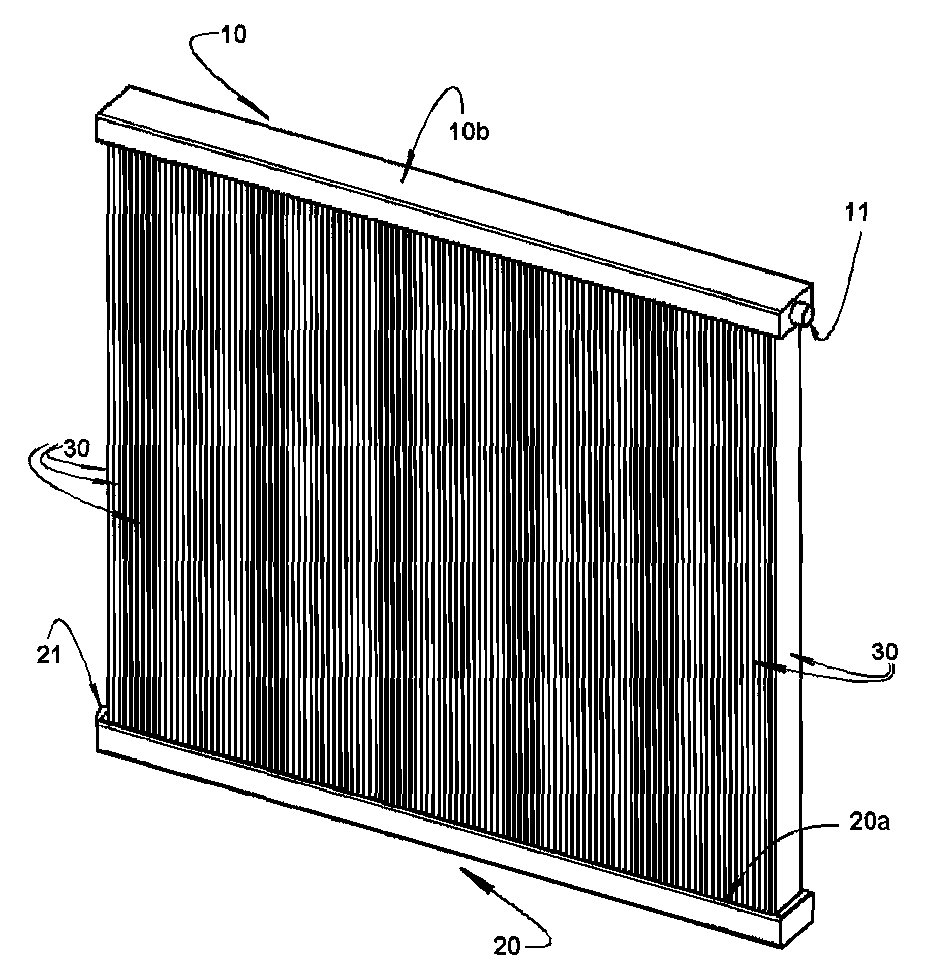
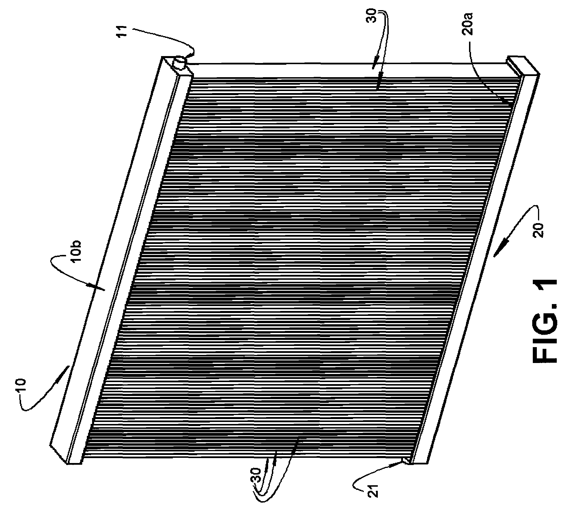
[0021]As already previously mentioned and illustrated in the enclosed drawings, the invention refers to the construction of a heat exchanger to be used as a condenser or as an evaporator in several applications, particularly in air conditioner appliances, said heat exchanger being of the single circuit type.

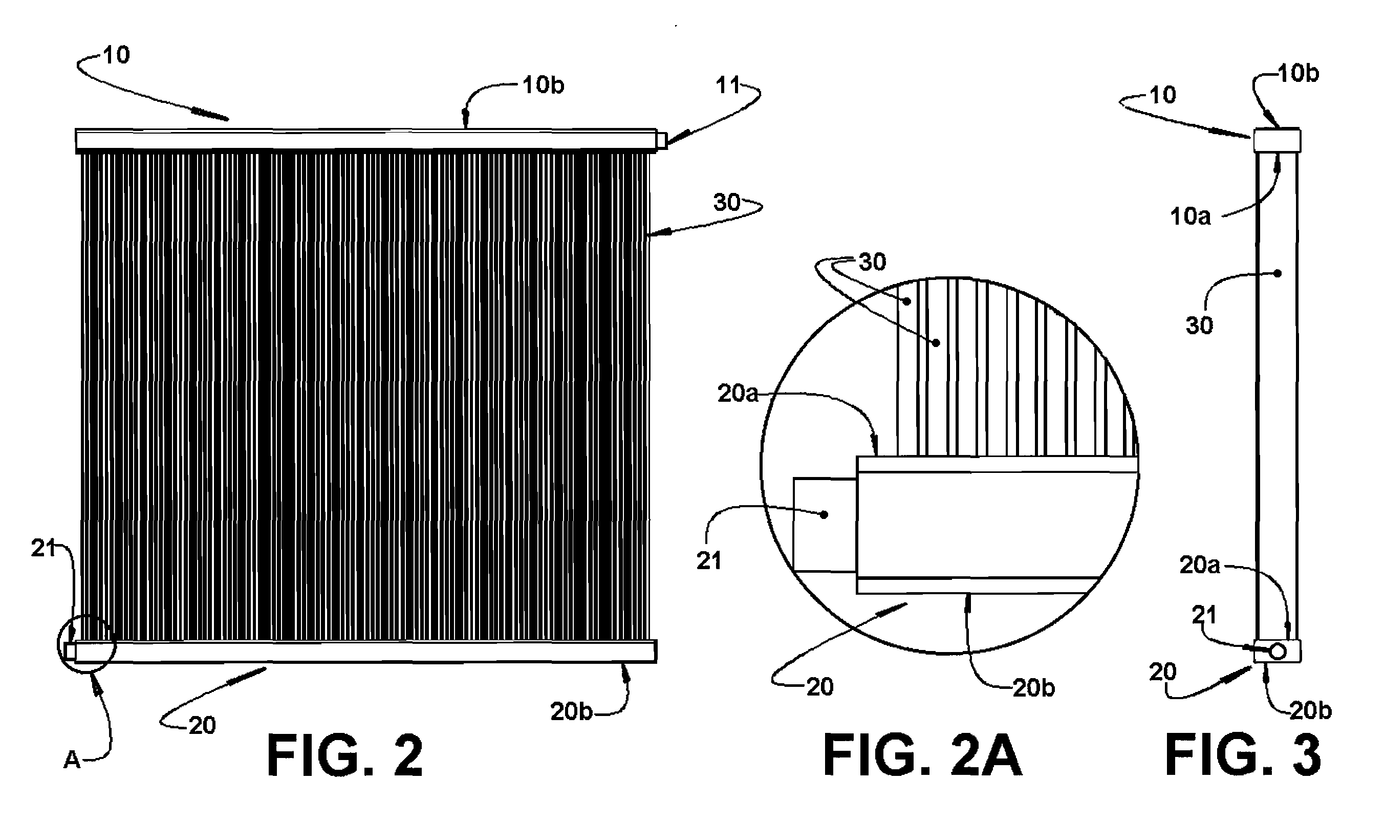
[0022]According to the present invention, the heat exchanger comprises an upper tubular head element 10 and a lower tubular head element 20, constructed in any adequate material, such as for example, carbon steel, stainless steel, thermoplastic material, etc., and which are horizontally arranged and have their ends closed, so that each tubular head element defines a tube extension whose cross section can vary according to the heat exchanger project. In the embodiment illustrated in the drawings, the upper tubular head element 10 and the lower tubular head element 20 present a rectangular cross section, having an inner longitudinal wall 10a, 20a turned to the heat exchanger struct...


PUM


Abstract

A heat exchanger of the single circuit type, to be coupled to a fluid circulation circuit and comprising: an upper tubular head element and a lower tubular head element horizontally arranged and which are each provided with a nozzle and through slots provided in an inner longitudinal wall portion; and a plurality of vertically disposed fluid conduction tubes, each internally defining a plurality of longitudinal microchannels. The opposite ends of the fluid conduction tubes are affixed to the inner longitudinal wall portion of the upper tubular head element and lower tubular head element, respectively, so as to communicate the ends of the microchannels of each tube with a through slot of the respective tubular head element and, thus, the fluid conduction tubes with the interior of the upper tubular head element and lower tubular head element.

Description

CROSS REFERENCE TO PRIOR APPLICATIONS[0001]This application claims priority to Brazilian Patent Application No. PI 0700912-7, filed on Mar. 13, 2007, the disclosure of which is incorporated herein by reference.[0002]1. Field of the Invention[0003]The present invention refers to a heat exchanger of the single circuit type to be used as a condenser or as an evaporator, in diverse applications, particularly in air conditioner appliances, aiming to facilitate the manufacture and to improve the heat exchange efficiency.[0004]2. Prior Art[0005]Nowadays, the heat exchangers manufactured with fluid conduction tubes of oval flat section, containing microchannels, are horizontally arranged with corrugated fins, being coupled to the vertically arranged head elements, at the side ends of the fluid conduction tubes, which form more than one circuit or are manufactured in the coil type configuration.[0006]This type of heat exchanger assembly, besides being of high industrial complexity, has the l...

Claims


Application Information

Patent Timeline
IPC IPC(8): F28F1/00
CPCF28F1/022F28D1/05383
Inventor HOENISCH, PAULO ROSSANOZATTAR, GUSTAVO HENRIQUE PACHECO
Owner WHIRPOOL SA
Learn More