
Charged particle accelerator

a particle accelerator and charge technology, applied in the direction of beam deviation/focusing, instruments, electric/magnetic means, etc., can solve the problems of unable to emit further field emission, the tip of the cathode evaporates or deforms, etc., and achieve the effect of increasing the capacity of a high-voltage power supply

Inactive Publication Date: 2008-09-18
HITACHI HIGH-TECH CORP
View PDF3 Cites 10 Cited by
  • Summary
  • Abstract
  • Description
  • Claims
  • Application Information

AI Technical Summary

Benefits of technology

[0009]Therefore, an object of the present invention is to provide a charged particle accelerator in which discharge is less likely to occur between a charged particle source and, an extraction electrode and an acceleration electrode.
[0012]According to the present invention, it is possible to provide a charged particle accelerator in which discharge is less likely to occur between a charged particle source and, an extraction electrode and an acceleration electrode without the need for increasing the capacity of a high voltage power supply for extraction.

Problems solved by technology

Particularly it is thought that when discharge occurs on the cathode, the current flowing through the cathode increases and due to Joule heat the tip of the cathode evaporates or deforms and a further field emission becomes impossible.
It is thought that the above problem attributable to such discharge can arise not only in electron microscopes but also in charged particle accelerators which irradiate a charged particle beam on a specimen.

Method used


Image

  • Charged particle accelerator
  • Charged particle accelerator
  • Charged particle accelerator

Examples


first embodiment

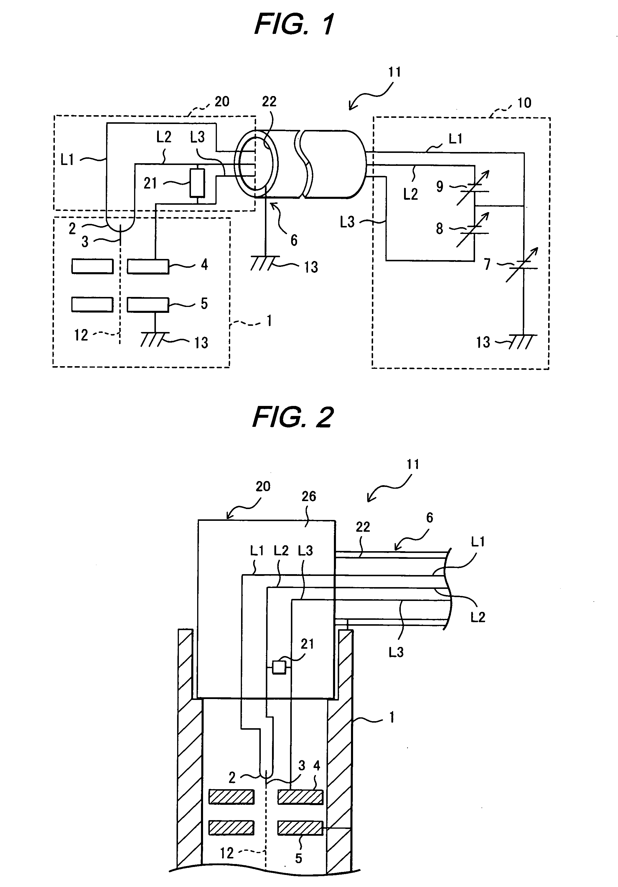
[0020]As shown in FIG. 1, an electron microscope 11 according to a first embodiment of the present invention has an electron gun chamber 1 the inside of which is kept at a low pressure. Inside the electron gun chamber 1 are a cathode 3 for emission of electrons 12 and a heating filament 2 for heating the cathode 3. The heating filament 2 is connected with the cathode 3 and supports the cathode 3.

[0021]Also, an extraction electrode 4 is located in the electron gun chamber 1. The extraction electrode 4 gives an intense electric field to the tip of the cathode 3 to extract electrons 12 from the cathode 3.

[0022]The electron gun chamber 1 also houses an acceleration electrode (ground electrode) 5. The acceleration electrode 5 is connected with a ground potential 13 and, when an intense electric field is given between the cathode 3 and the acceleration electrode 5, it accelerates electrons 12 extracted from the cathode 3.

[0023]Both ends of the heating filament 2 are connected with wire L1...

second embodiment

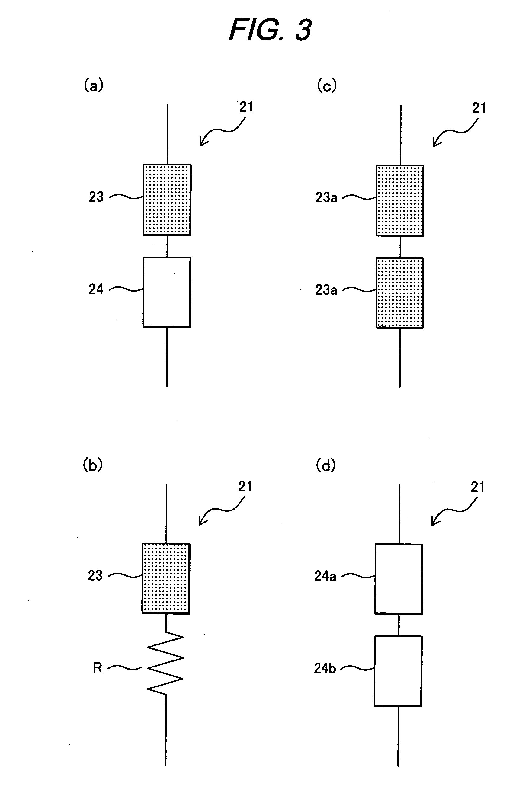
[0048]FIG. 4 shows the structure of the electron microscope 11 according to a second embodiment of the present invention and FIG. 5 is a sectional view of the electron gun chamber 1 of the charged particle accelerator 11 and its vicinity according to the second embodiment. The electron microscope 11 in the second embodiment is different from the electron microscope 11 in the first embodiment in that the surge absorber 21 is electrically connected between the charged particle source (cathode) 3 and the ground potential 13 (connection pattern 2a).

[0049]The connection pattern is not limited thereto but connection pattern 2b maybe selected in which unlike connection pattern 2a, the surge absorber 21 is not connected with wire L2 but is electrically connected between wire L1 connected with the cathode 3 and the ground potential 13.

[0050]Alternatively, connection pattern 2c may be selected in which the surge absorber 21 is electrically connected between wire L3 connected with the extracti...


PUM


Abstract

A charged particle accelerator in which discharge is less likely to occur between a charged particle source, and an extraction electrode, and an acceleration electrode without the need for increasing the capacity of a high voltage power supply for extraction. The charged particle accelerator includes a charged particle source which emits charged particles, an extraction electrode which extracts the charged particles from the charge particle source and an acceleration electrode which accelerates the extracted charged particles. A surge absorber is electrically connected between at least two of the charged particle source, the extraction electrode, and the acceleration electrode.

Description

CLAIM OF PRIORITY[0001]The present application claims priority from Japanese application serial No. 2007-64494 filed on Mar. 14, 2007, the content of which is hereby incorporated by reference into this application.[0002]1. Field of the Invention[0003]The present invention relates to a charged particle accelerator which emits charged particles and produces a charged particle beam and more particularly to an electron microscope which uses a charged particle beam as an electron beam.[0004]2. Background of the Invention[0005]Among various types of charged particle accelerators, the most widely used one is an electron microscope. The electron microscope has an electron gun chamber the inside of which is kept at a low pressure and the electron gun chamber houses a cathode as an electron source for emission of electrons, an extraction electrode for extraction of electrons from the cathode, and an acceleration electrode for acceleration of extracted electrons. The accelerated electrons cons...

Claims


Application Information

Patent Timeline
IPC IPC(8): G21K1/08
CPCB82Y10/00B82Y40/00H01J37/04H01J37/073H01J37/24H01J2237/3175H01J2237/0206H01J2237/04735H01J2237/06341H01J2237/26H01J2237/31701H01J37/3174
Inventor MORITA, HIROSHITAKEUCHI, RYOZOHATANAKA, AYUMU
Owner HITACHI HIGH-TECH CORP
Features
  • Generate Ideas
  • Intellectual Property
  • Life Sciences
  • Materials
  • Tech Scout
  • Unparalleled Data Quality
  • Higher Quality Content
  • 60% Fewer Hallucinations
Learn More