Transmission Line Structure for Power Line Communication and Power Line Switch Used Therein

a technology of transmission line and power line switch, which is applied in the direction of transmission, power distribution line transmission, dc network circuit arrangement, etc., can solve the problems of reducing the capacity of transmittable, affecting the transmission of plc signals, and inconvenient communication in the home and local area wiring, so as to prevent unwanted transmission of information, maintain power line communication, and reduce communication convergence

Inactive Publication Date: 2008-09-18
YAMAHA CORP
View PDF6 Cites 29 Cited by
  • Summary
  • Abstract
  • Description
  • Claims
  • Application Information

AI Technical Summary

Benefits of technology

[0008]It is an object of the present invention to provide a transmission line structure for power line communication, capable of smoothly performing power line communication even using a power line having a switch and / or a branch, and to provide a power line switch used for the transmission line structure for power line communication.
[0019]According to the present invention, by also providing the power line filter in series to the switch section, a PLC signal can always pass via the by-pass circuit, thereby allowing a PLC signal to be transmitted all time under the same conditions regardless of the on / off status of the switch section.
[0020]Further according to the present invention, providing the by-pass circuit and further providing the signal selection section in the by-pass circuit can select or sort a PLC signal according to the content thereof, thereby preventing unwanted transmission of information to ensure and maintain security and reducing convergence in communication.

Problems solved by technology

It is likely that, unlike the high-voltage transmission line, the indoor and local area wirings, however, are not suitable for communication due to the structure of their wirings, which may have switches including a circuit breaker midstream and / or wiring branches.
Also there is a problem where any branch in the power line causes extreme variation in high-frequency impedance at a branch point, which results in the degradation of transmission of PLC signals.
There are further problems, including in security, due to the same PLC signals being transmitted to the entire branches, as well as problems of convergence, that is likely caused due to reduction of the capacity of transmittable communication data because of the transmission of the same signal to the entire branches.

Method used


Image

  • Transmission Line Structure for Power Line Communication and Power Line Switch Used Therein
  • Transmission Line Structure for Power Line Communication and Power Line Switch Used Therein
  • Transmission Line Structure for Power Line Communication and Power Line Switch Used Therein

Examples


first embodiment

[0025]Referring to the drawings, the configuration of a circuit breaker is described, which constitutes the present invention. This circuit breaker is configured so as to pass a PLC (power line communication) signal from the primary side to the secondary side and vice versa, regardless of the make / break status of a contact.

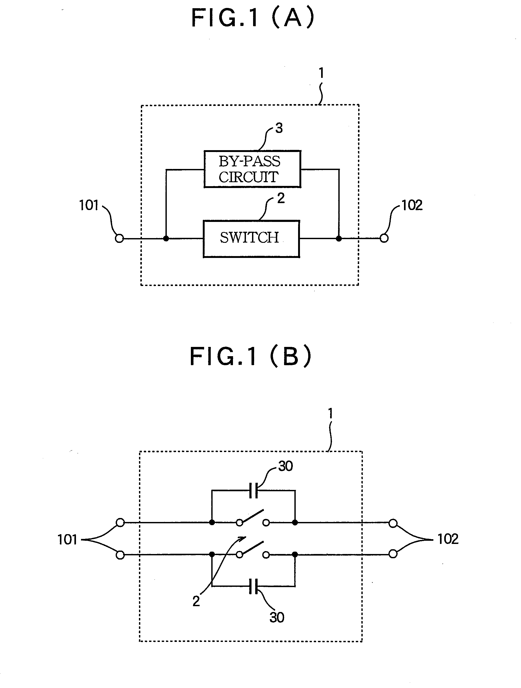
[0026]FIG. 1 shows the configuration of a circuit breaker, which constitutes a first embodiment of the present invention. Shown in (A) of the same figure is the block diagram showing the function of each part. The circuit-breaker 1 has a primary side terminal 101 connecting to the primary side (power supply side) and a secondary side terminal 102 connecting to the secondary side (load side) of the power line. The circuit breaker has a switch 2 and a by-pass circuit 3 that are connected in parallel between the primary side terminal 101 and the secondary side terminal 102. The switch 2 normally makes electrical connection between the primary side terminal 101 and th...

second embodiment

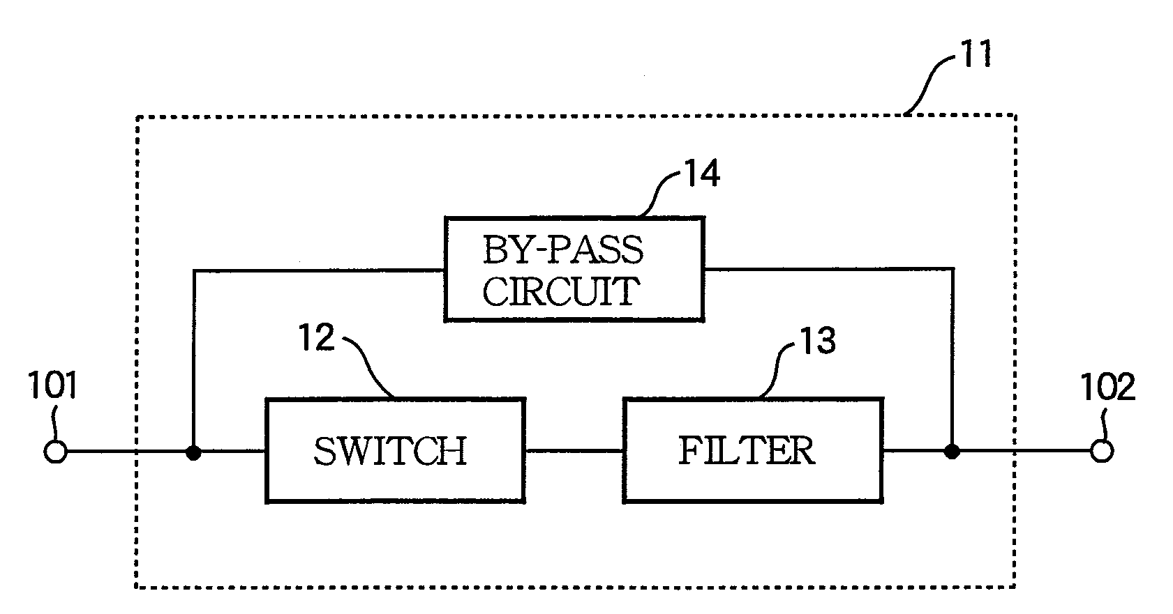
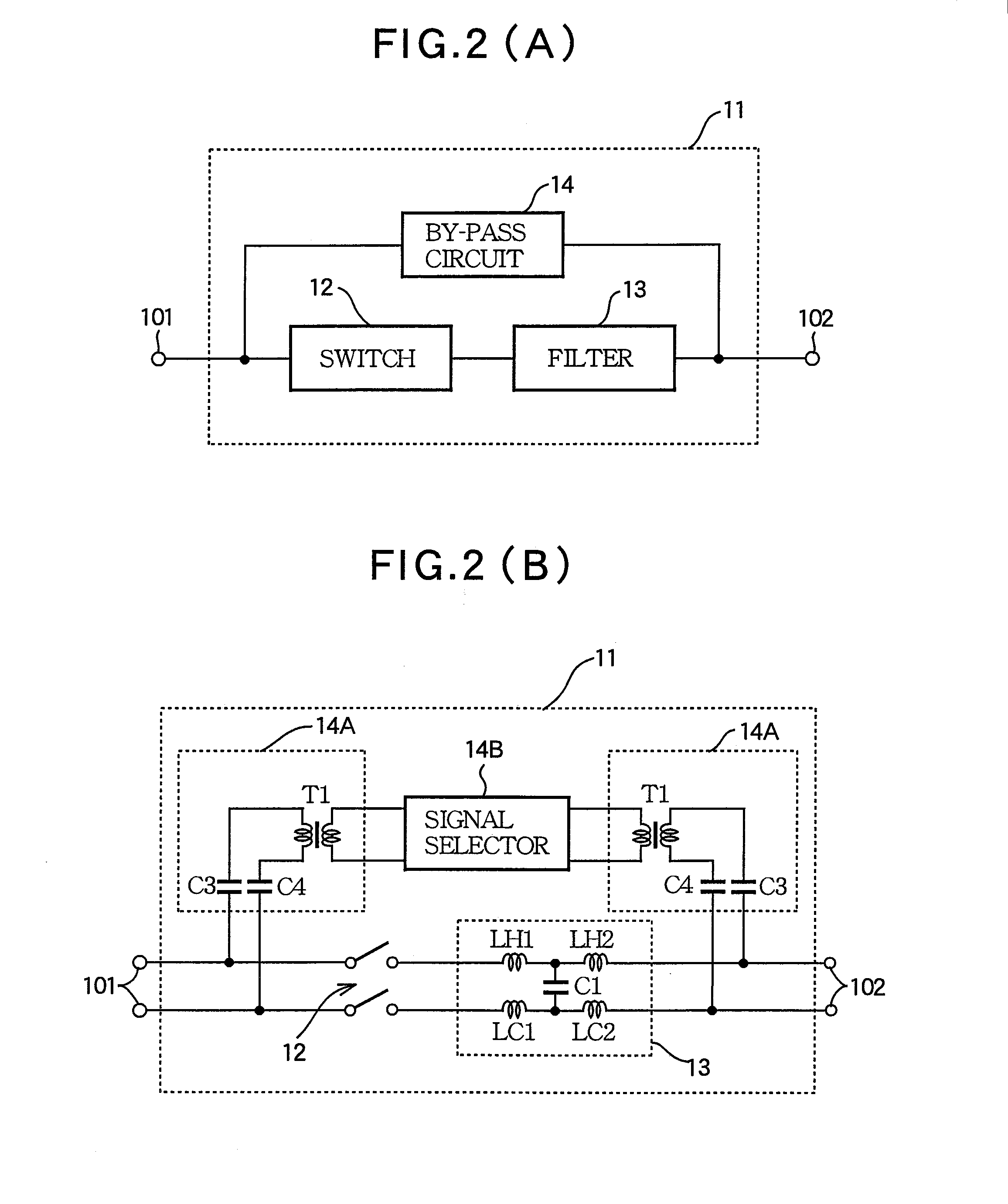
[0033]FIG. 2 shows the configuration of a circuit breaker, which constitutes the present invention. The diagram (A) of the same figure is the block diagram showing the function of each part; while the diagram (B) is the diagram showing an example circuit structure of the circuit breaker.

[0034]The circuit breaker 11 includes a primary terminal 101 connected to the primary side (power supply side) and a secondary terminal 102 connected to the secondary side (load side) of the power line. A switch 12 and a power line filter 13 are connected in series between the primary side terminal 101 and the secondary side terminal 102. And a by-pass circuit 14 is connected in parallel with the switch 12 and the power line filter 13 connected in series.

[0035]The switch 12 normally makes electrical connection between the primary side terminal 101 and the secondary side terminal 102. It cuts off (disconnects) the connection when the secondary side current exceeds the rated current value (20A, for exa...

third embodiment

[0045]FIG. 3 is the block diagram showing a transmission path structure for power line communication, which constitutes the present invention. This diagram shows the configuration of a circuit of a distribution board 20. In the distribution board 20, power supply is branched into four downstream power lines, and each of circuit breakers 21-1˜4 is inserted in each of the branched power lines, respectively.

[0046]A power line wiring 26 connected to a primary side (power supply side) terminal 101 of the distribution board 20 is branched into four downstream lines, each of which is connected to each of secondary side (load side) terminals 102-1˜4 via each of the circuit breakers 21-1˜4, respectively.

[0047]Each circuit breaker 21 includes a switch 22 and a power line filter 23. Since this configuration is similar to that of the switch 12 and the power line filter 13 in the embodiment in FIG. 2, the detailed information is omitted. Thus a PLC signal does not pass through the circuit breake...


PUM


Abstract

A power line switch apparatus is provided for use in a power line communication system that transmits a signal through a power line that feeds a power supply current. In the power line switch apparatus, a switch section is inserted in the power line to make or break connection of the power line. A power line filter is connected in series to the switch section and inserted in the power line, the power line filter being used to pass the power supply current and to cut off the signal of the power line communication system. A by-pass circuit is connected in parallel with the series connection of the switch section and the power line filter, the by-pass circuit including a by-pass filter for cutting off the power supply current and passing the signal of the power line communication system.

Description

BACKGROUND OF THE INVENTION[0001]1. Field of the Invention[0002]The present invention relates to a transmission line structure for smooth PLC: Power Line Communication via a distribution board and / or a circuit breaker, and to a power line switch used in the transmission line structure for the power line communication.[0003]2. Background Art[0004]Now, power line communication for performing digital communication by means of power line wirings distributed across the country is going to be put to practical use. This power line communication mainly applies to short-distance communication networks using indoor or local area wiring or ‘last mile’ connection wiring rather than to long-distance telecommunication using high-voltage transmission line (Non-patent document 1).[0005]Non-patent document 1: “Report”, online, December, 2005, Society concerning the high-speed electric power line transportation communication, searched on Feb. 23, 2007, Internet URL: http: / / www.soumu.go.jp / s-news / 2005...

Claims


Application Information

Patent Timeline
Patent Type & Authority Applications(United States)
IPC IPC(8): H04B3/54H04B3/56
CPCH04B2203/5491H04B3/56
Inventor YAMAZAKI, SHOHEI
Owner YAMAHA CORP
Why Eureka
Try Eureka