
Electrode sheet, method of manufacturing the electrode sheet and plasma display panel having the electrode sheet

Inactive Publication Date: 2008-09-18
SAMSUNG SDI CO LTD
View PDF6 Cites 0 Cited by
  • Summary
  • Abstract
  • Description
  • Claims
  • Application Information

AI Technical Summary

Benefits of technology

[0012]Aspects of embodiments of the present invention are directed toward an electrode sheet capable of simplifying a manufacturing process, a method of manufacturing the electrode sheet, and a plasma display panel having the electrode sheet.
[0013]Other aspects of embodiments of the present invention are directed toward an electrode sheet having improved physical properties such as abrasion resistance, heat resistance and voltage resistance, a method of manufacturing the electrode sheet, and a plasma display panel having the electrode sheet.

Problems solved by technology

For example, a DC surface emitting structure has a low luminous efficiency.
However, it is difficult to uniformly form a plurality of dielectric layers on the electrode surface having a thickness ranging from several tens to 100 μm, productivity is low due to the complicated manufacturing process, and / or voltage resistance characteristics are deteriorated due to field focusing.

Method used


Image

  • Electrode sheet, method of manufacturing the electrode sheet and plasma display panel having the electrode sheet
  • Electrode sheet, method of manufacturing the electrode sheet and plasma display panel having the electrode sheet
  • Electrode sheet, method of manufacturing the electrode sheet and plasma display panel having the electrode sheet

Examples


first embodiment

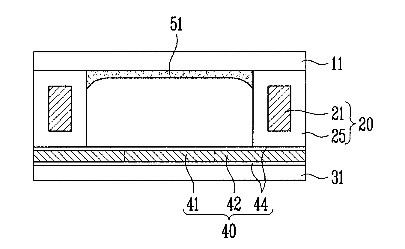
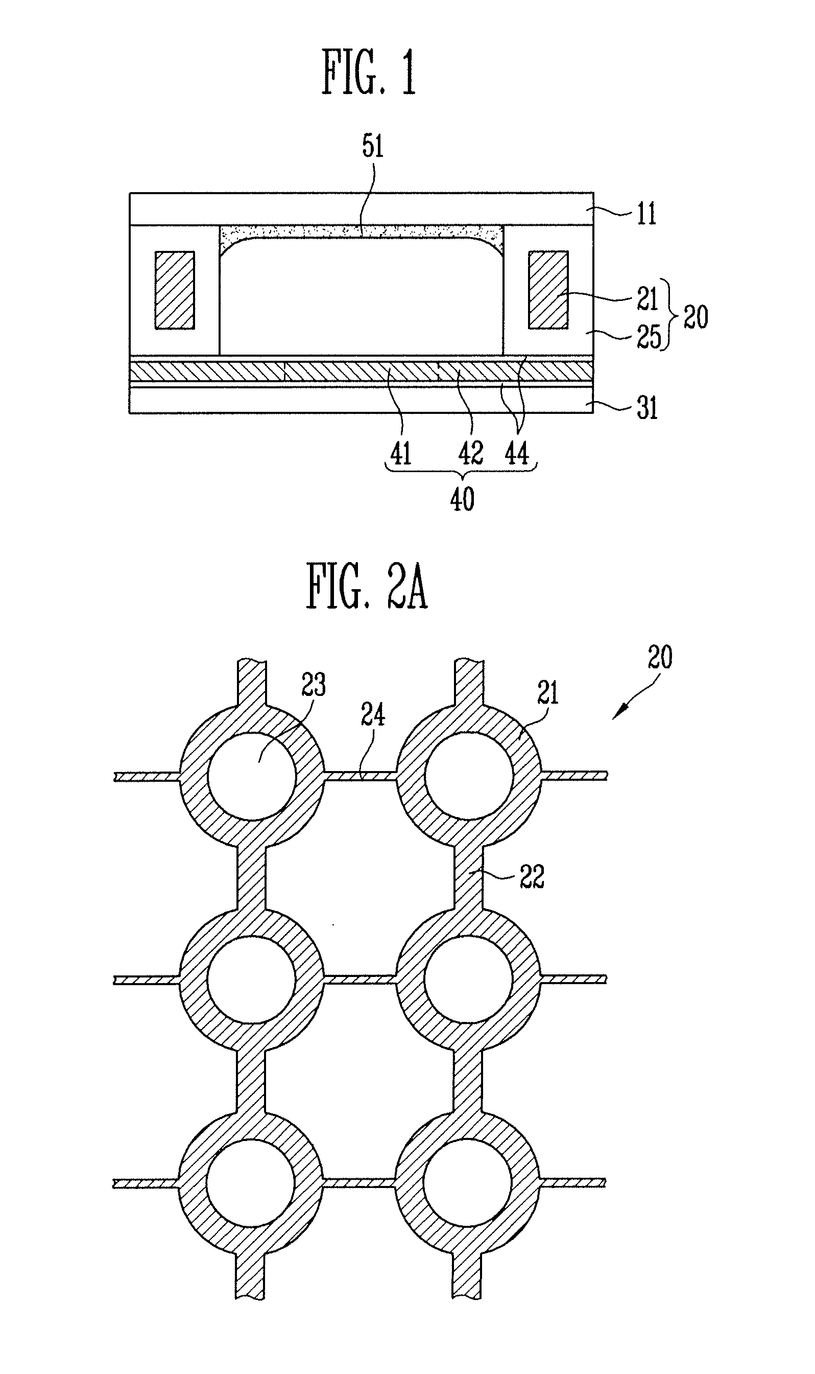
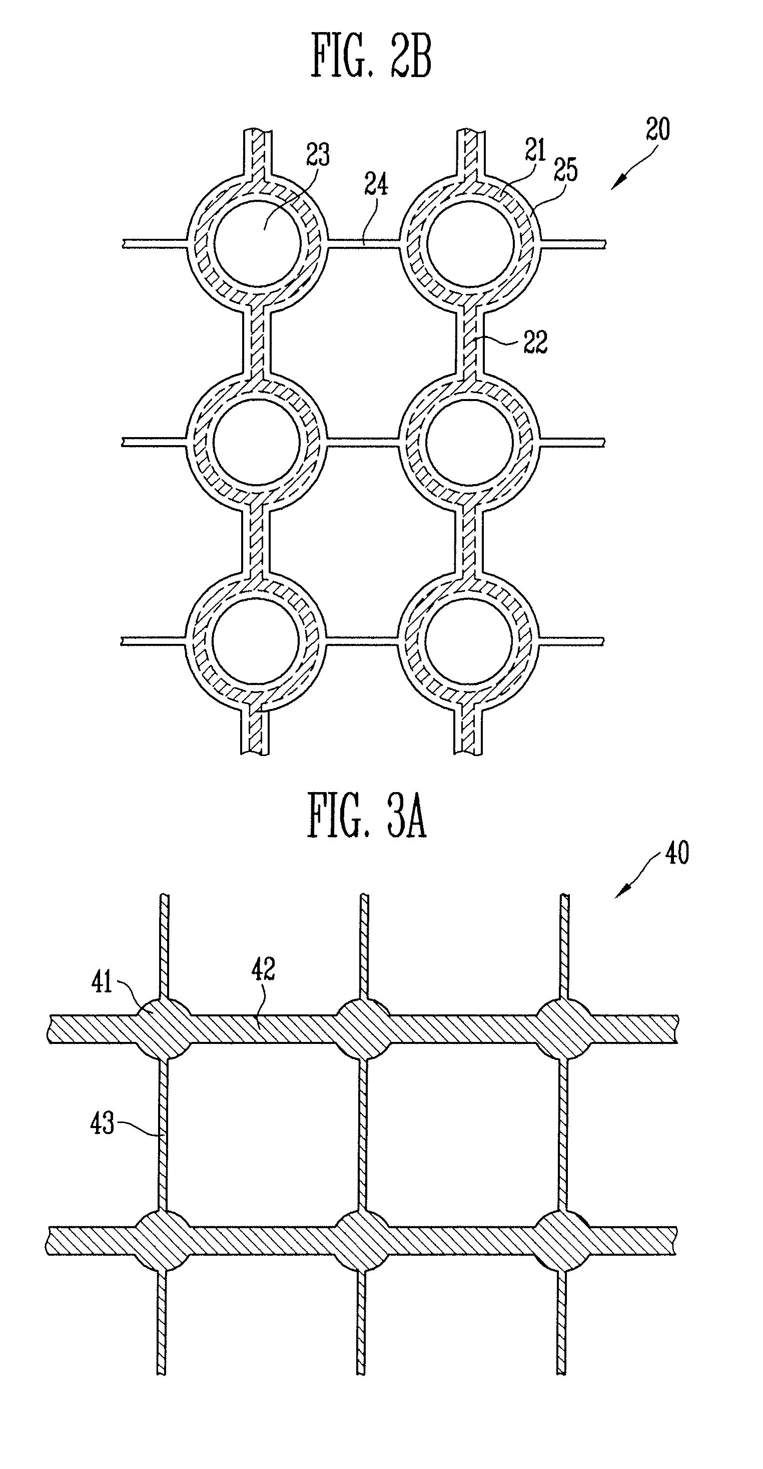
[0027]FIG. 1 is a cross-sectional view showing a plasma display panel according to the present invention. In FIG. 1, one pixel is schematically shown for convenience purposes. FIG. 2A and FIG. 2B and FIG. 3A and FIG. 3B are plan views showing a first electrode sheet and a second electrode sheet.

[0028]Referring to FIG. 1 and FIG. 2B, a first electrode sheet 20 is arranged on one surface of a first substrate 11. The first electrode sheet 20 includes a plurality of first electrodes 21, a first electrode line 22, and a dielectric 25. The first electrodes 21 are formed at constant (or substantially constant) distances apart, and each of the first electrodes 21 has a discharge space 23 formed in its central region. The first electrode line 22 connects the first electrodes 21 arranged in (or along) a first direction, and the dielectric 25 encloses (or encases or encapsulates) the first electrodes 21 and the first electrode line 22 and connects the first electrodes 21 arranged in (or along)...

second embodiment

[0038]FIG. 4 is a cross-sectional view showing a plasma display panel according to the present invention. In FIG. 4, one pixel is schematically shown for convenience purposes. FIG. 5A and FIG. 5B are plan views showing a first electrode sheet and a second electrode sheet.

[0039]Referring to FIG. 4 and FIG. 5A, a first electrode sheet 120 is arranged on one surface of a first substrate 111. The first electrode sheet 120 includes a plurality of first electrodes 121, a first electrode line 122 and a dielectric 125. The first electrodes 121 are arranged at constant (or substantially constant) distances, and each of the first electrodes 121 has a discharge space 123 formed in its central region. The first electrode line 122 connects the first electrodes 121 arranged in (or along) a first direction, and the dielectric 125 encloses (or encases or encapsulates) the first electrodes 121 and the first electrode line 122 and connects the first electrodes 121 arranged in (or along) a second dire...


PUM


Abstract

An electrode sheet, a method of manufacturing the electrode sheet, and a plasma display panel having the electrode sheet. The electrode sheet includes: a plurality of electrodes arranged at substantially constant distances apart, each of the electrodes having a discharge space in its central region; an electrode line for connecting the electrodes along a first direction; and a dielectric enclosing the electrodes and the electrode line and connecting the electrodes along a second direction, wherein the electrodes and the electrode line are composed of magnesium (Mg), and the dielectric is composed of magnesium oxide (MgO).

Description

CROSS-REFERENCE TO RELATED APPLICATION[0001]This application claims priority to and the benefit of Korean Patent Application No. 10-2007-0026196, filed on Mar. 16, 2007, in the Korean Intellectual Property Office, the entire content of which is incorporated herein by reference.BACKGROUND[0002]1. Field of the Invention[0003]The present invention relates to an electrode sheet, a method of manufacturing the electrode sheet, and a plasma display panel having the electrode sheet[0004]2. Discussion of Related Art[0005]In recent years, there is an increasing need for a large flat panel display. As such, there are active attempts to develop a plasma display panel (PDP) having a large panel that can be easily manufactured.[0006]Generally, a plasma display panel includes a plurality of pixels arranged in a matrix. The pixels are selected by address discharge using an image data, and a phosphor is excited by ultraviolet rays generated during a continuous sustain discharge procedure to emit vis...

Claims


Application Information

Patent Timeline
IPC IPC(8): H01J9/02H01J17/49
CPCH01J9/02H01J9/242H01J11/16H01J2211/361H01J11/36H01J2211/225H01J11/22H01J11/38
Inventor HWANG, YONG-SHIKYI, WON-JUKANG, KYOUNG-DOOCHOI, JONG-WOOCHUN, BYOUNG-MINKWON, JAE-IK
Owner SAMSUNG SDI CO LTD
Learn More