Photovoltaic Power Output-Utilizing Device

a technology of photovoltaic power output and power output range, which is applied in the direction of photovoltaic energy generation, secondary cell charging/discharging, photovoltaic power output, etc., can solve the problems of poor situation, insufficient power output at these light intensities, and insufficient voltage rang

Inactive Publication Date: 2008-09-18
ECOSOL SOLAR TECH USA
View PDF7 Cites 163 Cited by
  • Summary
  • Abstract
  • Description
  • Claims
  • Application Information

AI Technical Summary

Benefits of technology

[0015]In yet another embodiment of the invention, the device may be for charging an electrical energy storage device. In this embodiment, the DC / DC power converter is capable of increasing capacitor assembly output discharge voltages to a storage device charge voltage, and the device would comprise a direct discharge path to the energy storage device. In particular, the device would comprise a means for charging the energy storage device through the DC / DC power converter when the capacitor assembly discharge voltage needs to be increased, and a means for charging the energy storage device directly by a direct charging path when the capacitor assembly discharge voltage is not less than the charging voltage.
[0016]These and other features of the invention will be more fully understood by references to the following drawings.

Problems solved by technology

While the device of G Mellors et al. is useful, any light intensity to which the photovoltaic assembly is subjected, which can not generate a voltage greater than the combined voltage of the battery and the diode, will not activate the photovoltaic assembly to output a charge current.
As a result, power outputs at these light intensities are not utilized.
This situation worsens as the battery voltage increases as it is being charged.
This range of voltages will not provide the greatest power output that the photovoltaic assembly is capable of providing.

Method used


Image

  • Photovoltaic Power Output-Utilizing Device
  • Photovoltaic Power Output-Utilizing Device
  • Photovoltaic Power Output-Utilizing Device

Examples


Embodiment Construction

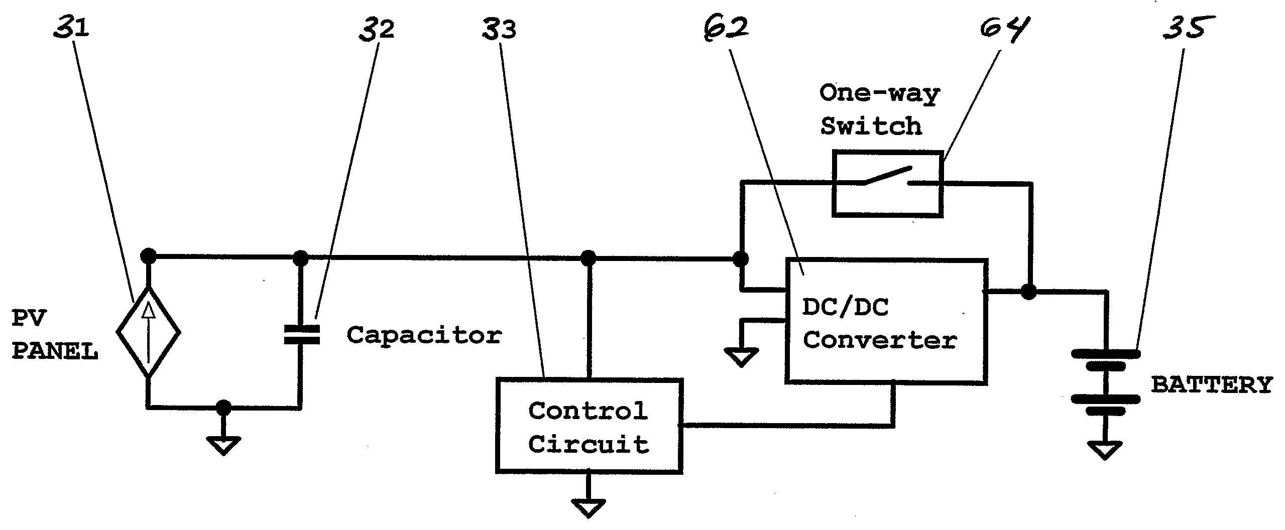
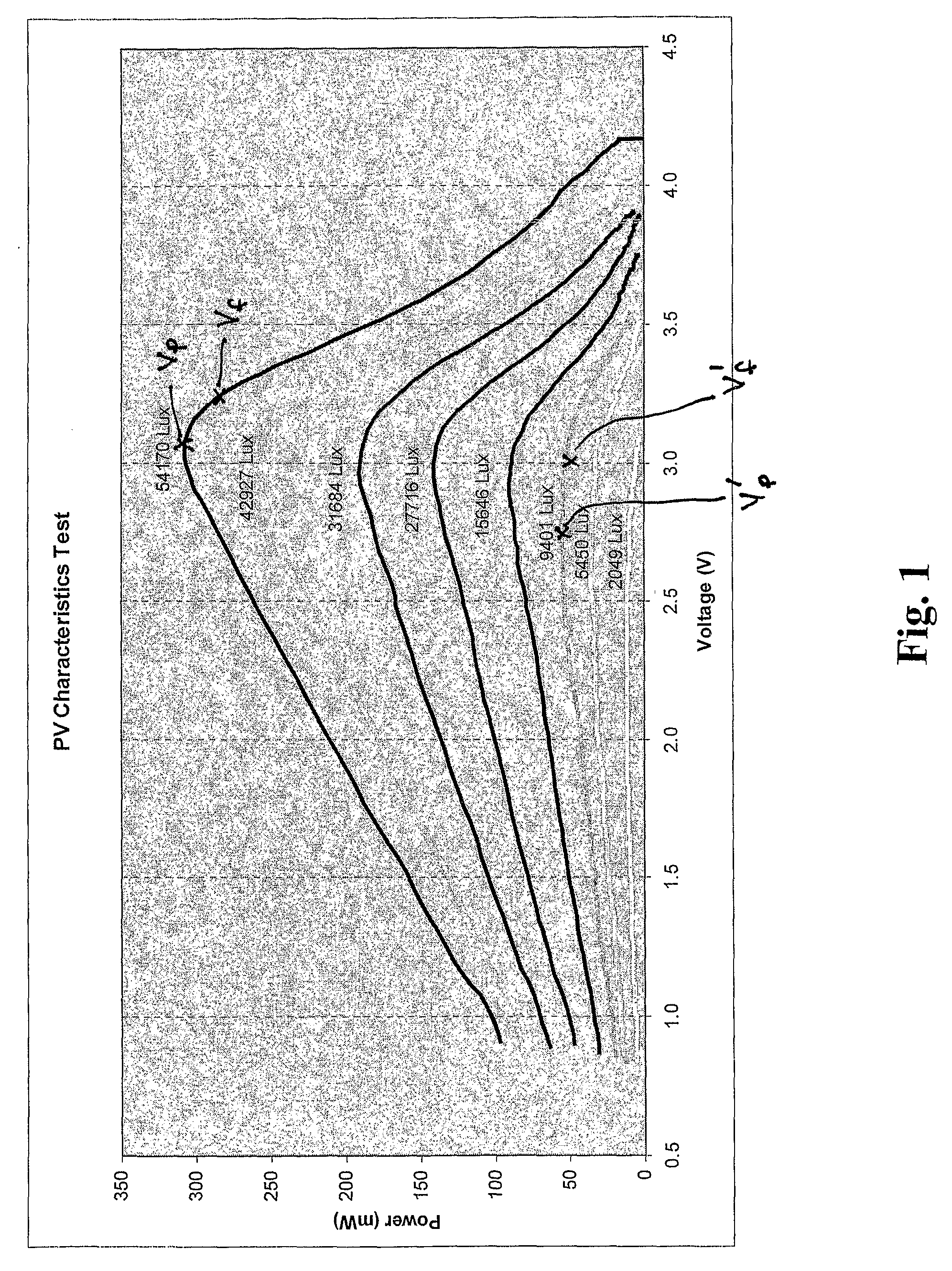
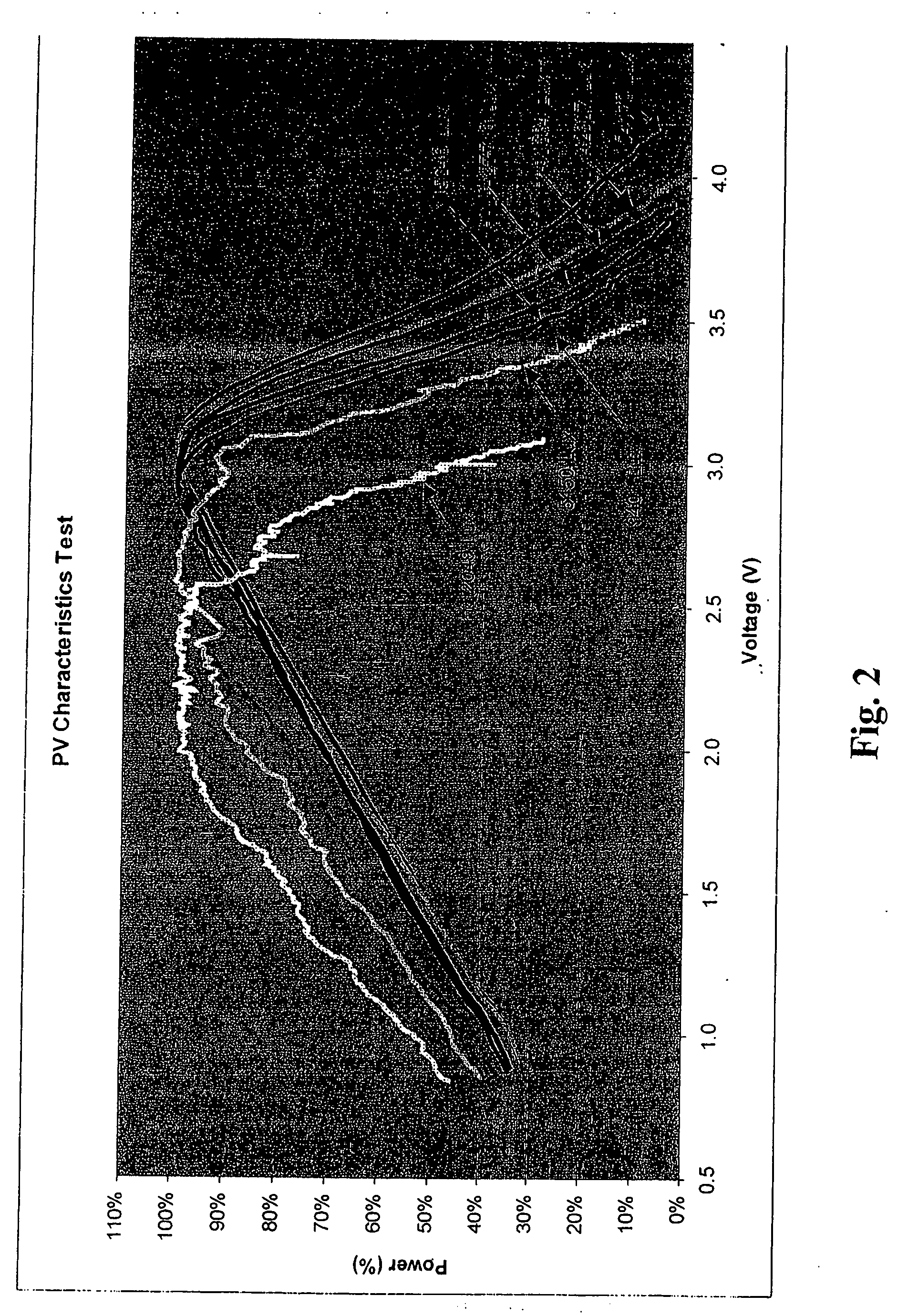
[0023]The present invention relates to optimizing the performance of a photovoltaic (PV) assembly with respect to the light intensity it receives. In developing this invention, Applicants performed tests to measure how the power output of a typical photovoltaic assembly was affected by the light intensity. These tests were conducted by Applicants using a photovoltaic assembly in the form of a PV panel with eight cells in series connection. The results of these tests are shown in FIG. 1 where the PV panel power outputs (“Power (mW)”) for different light intensities on the PV panel are plotted against the PV panel output voltage (“Voltage (V)”).

[0024]The graph illustrates that when the light intensity remains substantially unchanged, the power (mW) increases with the output voltage (V) also increasing until the Power (mW) peaks; from where the voltage (V) will continue to increase while the power (mW) declines. Utilizing this phenomenon, Applicants have arrived at the present inventio...


PUM


Abstract

Briefly described, the invention provides a photovoltaic assembly power output utilizing device which partially charges a capacitor assembly. This capacitor assembly is then partially discharged by a DC/DC power converter in different ranges of voltages in which the power output from the photovoltaic assembly peaks for different light intensities.

Description

FIELD OF THE INVENTION[0001]The present invention relates to a photovoltaic power output-utilizing device.BACKGROUND OF THE INVENTION[0002]In, for example, U.S. Pat. No. 3,921,049, issued to G. Mellors et al. on Nov. 18, 1975, a photovoltaic assembly for charging a battery is described. The photovoltaic assembly is simply connected to the battery to be charged with a diode between them. This diode prevents reverse current flow when the photovoltaic assembly is not subjected to sufficient light intensity for the photovoltaic assembly output voltage to be greater than the battery voltage plus the diode forward voltage.[0003]While the device of G Mellors et al. is useful, any light intensity to which the photovoltaic assembly is subjected, which can not generate a voltage greater than the combined voltage of the battery and the diode, will not activate the photovoltaic assembly to output a charge current. As a result, power outputs at these light intensities are not utilized. This situ...

Claims


Application Information

Patent Timeline
Patent Type & Authority Applications(United States)
IPC IPC(8): H02J7/00H01L31/04
CPCH02J7/35H02J7/345Y02E10/566H02S40/38Y02E10/56Y02E70/30
Inventor ZHU, ZUOHANGKULAR, ANDREW C.
Owner ECOSOL SOLAR TECH USA
Why Eureka
Try Eureka