Image information processing apparatus
- Summary
- Abstract
- Description
- Claims
- Application Information
AI Technical Summary
Benefits of technology
Problems solved by technology
Method used
Image

Examples
embodiment 1
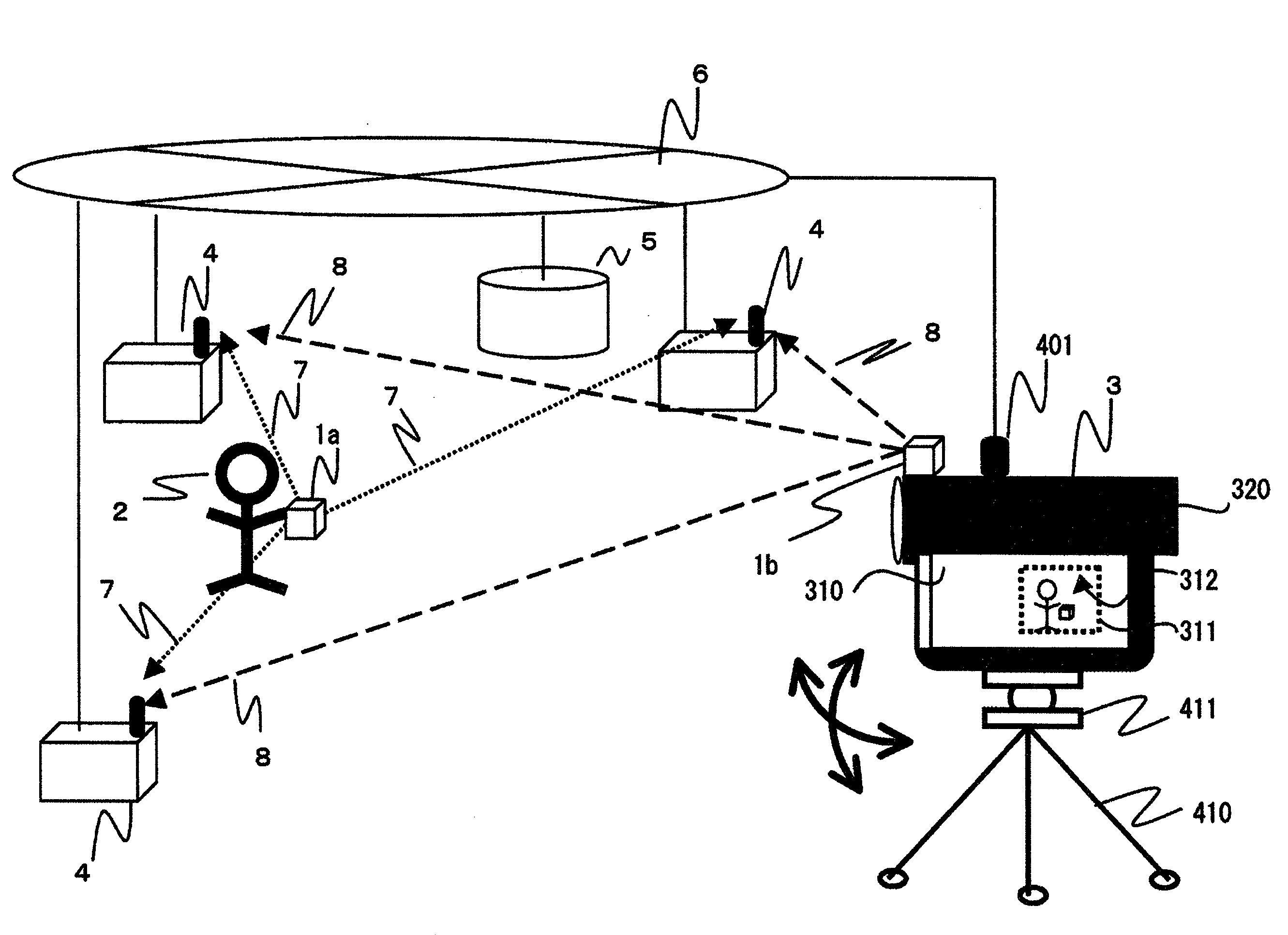
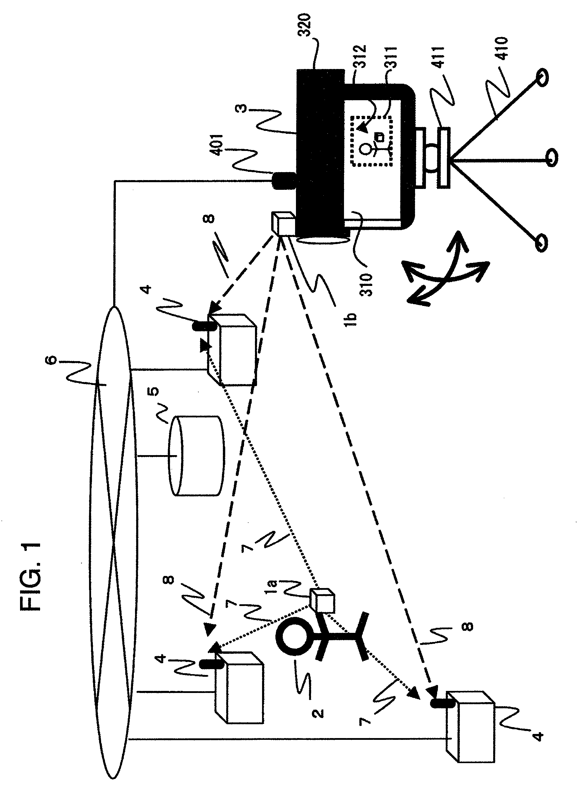
[0022]FIG. 1 depicts an exemplary system configuration of an image information processing apparatus with the aid of a wireless integrated circuit (IC) tag in accordance with one embodiment of the invention.
[0023]A photographic object 2 is a target subject of shooting, e.g., a person. This shooting subject 2 has a carriable wireless IC tag 1a for use as an identification (ID) information output device. The wireless IC tag 1a functions to transmit over the air a radio-frequency information signal 7 indicative of an ID unique thereto. This ID information signal 7 may include at least its unique ID information and a position measurement signal along with other data signals.
[0024]A video camera 3 with a built-in image pickup module such as an image sensor (not shown) is arranged to have a wireless IC tag 1b functioning as an ID information output unit, which tag may be externally attached to or internally built in the video camera 3. The wireless IC tag 1b transmits over-the-air an inher...
embodiment 2
[0038]FIG. 3 illustrates one example of a system configuration of an image information processing apparatus using a wireless IC tag in accordance with another embodiment of the invention. The same reference numerals are used to indicate the same parts or components as those shown in FIG. 1, and a detailed explanation thereof is eliminated herein.
[0039]A video camera 3 of FIG. 3 has, as a radio receiver unit 4 to be later described, part of various types of connection devices and respective constituent components in order to detect a present position of a wireless IC tag 1a owned by a shooting subject 2. As an example, this embodiment has the radio receiver unit 4 including a communication unit 401, a tripod 410, a camera platform 411, a lens hood 412, a microphone 413, a housing 414 with LCD panel 310 received therein, a remote commander 415 for remote control of the video camera 3, a remote controller 416 for manipulation of the tripod 410, and a main-body 417 of the video camera 3...
embodiment 3
[0045]FIGS. 5A to 5E show an exemplary system configuration of wireless tag-used image information processing apparatus also embodying the invention and several ways of displaying a sensed image on LCD panel.
[0046]In FIG. 5A, a vertical axis is shown on the left hand side, which indicates some levels of the order of priority. The higher the level, the higher the priority. More precisely, a shooting subject 2a is the highest in priority, followed by 2b, 2c and 2d.
[0047]As shown in FIG. 5B, the video camera 3 is operatively associated with a priority order setup unit 340. In this embodiment the shooting subjects 2a-2d have wireless IC tags 1a-1d, respectively. The priority orders of these tags are set up by the priority setter 340 via wired or wireless data transfer channels. The priority setup may be done prior to shooting or alternatively may be changed in responding to an instruction from the user. The wireless IC tags may be designed so that their priorities are updated automatica...
PUM
 Abstract
Description
Claims
Application Information
 - Generate Ideas
- Intellectual Property
- Life Sciences
- Materials
- Tech Scout
- Unparalleled Data Quality
- Higher Quality Content
- 60% Fewer Hallucinations
Browse by: Latest US Patents, China's latest patents, Technical Efficacy Thesaurus, Application Domain, Technology Topic, Popular Technical Reports.
© 2025 PatSnap. All rights reserved.Legal|Privacy policy|Modern Slavery Act Transparency Statement|Sitemap|About US| Contact US: help@patsnap.com