Exposure apparatus and device manufacturing method

Inactive Publication Date: 2008-09-18
NIKON CORP
View PDF27 Cites 22 Cited by
  • Summary
  • Abstract
  • Description
  • Claims
  • Application Information

AI Technical Summary

Benefits of technology

[0008]According to this apparatus, the object carrier system can carry an object to the holding device that the holding device carrier system holds, or can carry out an object from the holding device that the holding device carrier system holds under a reduced-pressure environment. That is, the object carrier system makes it possible to perform object exchange on the holding device held by the holding device carrier system. Accordingly, even if it takes a relatively lon

Problems solved by technology

However, the wafer holder by the electrostatic chuck method has a longer response time when compared to the vacuum chuck.
More specifically, the wafer holder by the electrostatic chuck method requires a relatively long time after placing a wafer on a wafer holder until electrostatic force has been started and a predetermined adhes

Method used


Image

  • Exposure apparatus and device manufacturing method
  • Exposure apparatus and device manufacturing method
  • Exposure apparatus and device manufacturing method

Examples


Embodiment Construction

[0019]Hereinafter, an exposure apparatus 10 related to an embodiment of the present invention will be described, referring to FIGS. 1 to 6B.

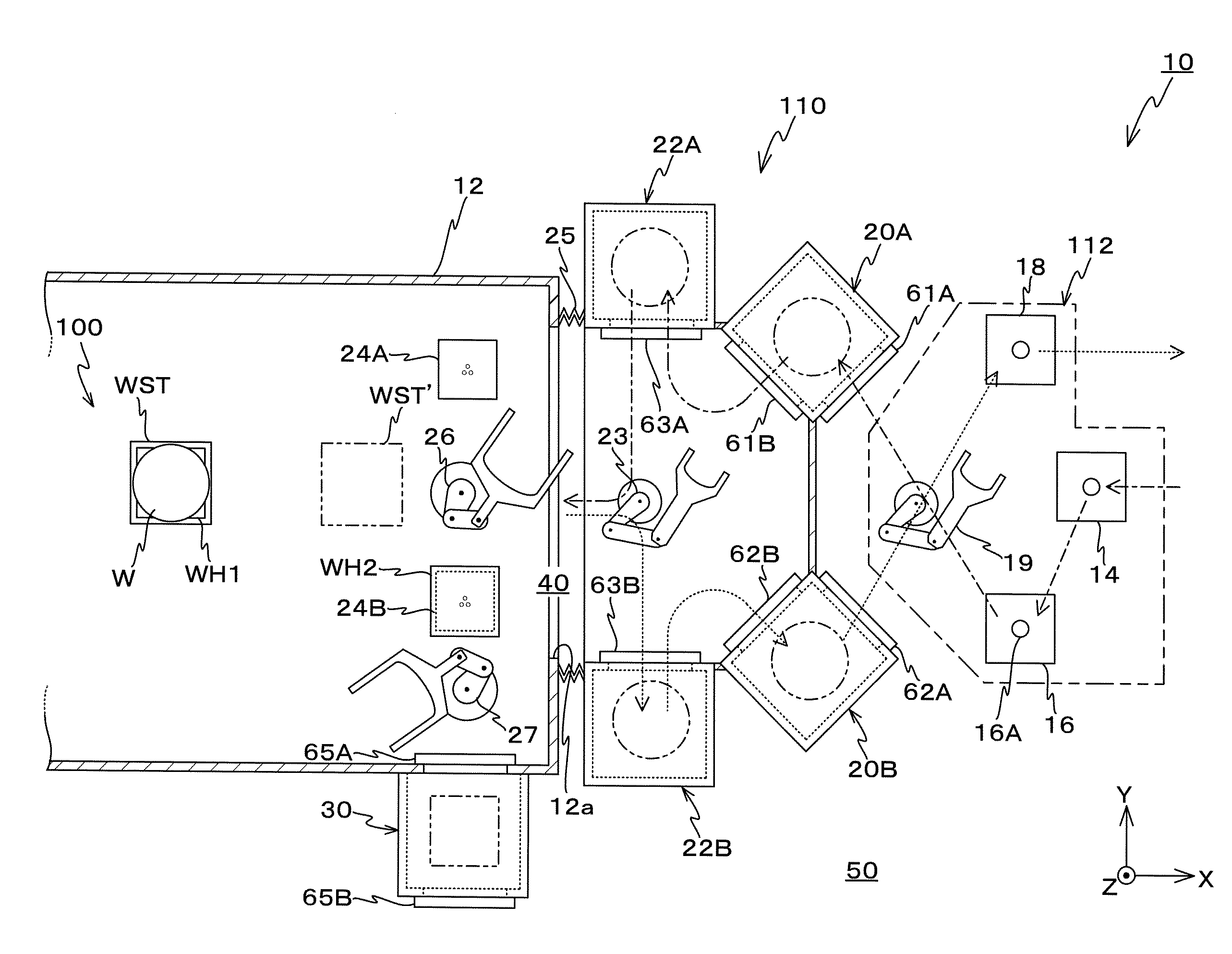
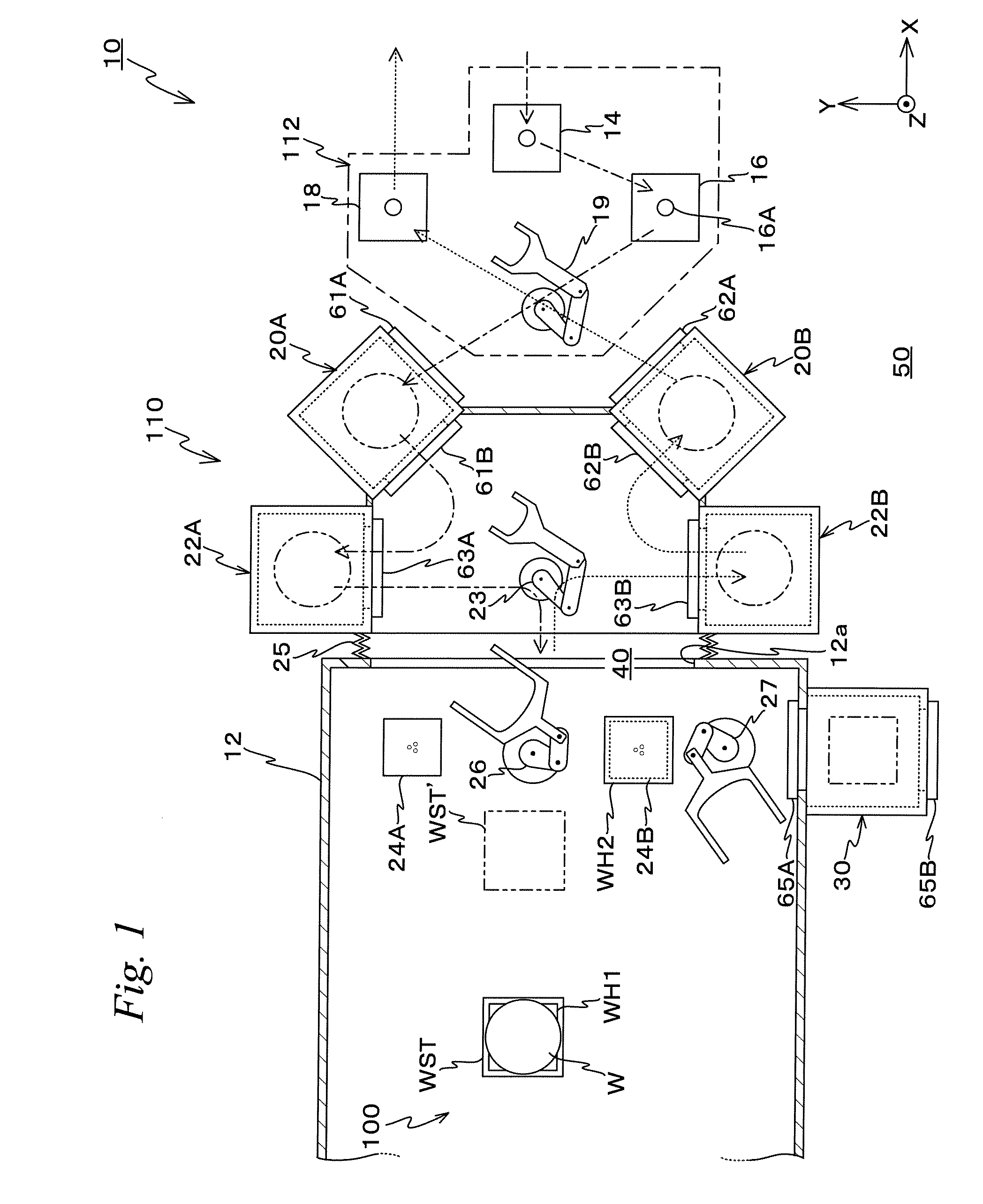
[0020]FIG. 1 shows a planar view of a schematic configuration of exposure apparatus 10 related to the embodiment. Exposure apparatus 10 is equipped with an atmospheric carrier system 112 placed in an atmospheric pressure space 50, a vacuum carrier system 110 placed on the −X side of atmospheric carrier system 112, and a main body chamber 12 placed on the −X side of vacuum carrier system 110.

[0021]Between vacuum carrier system 110 and an opening 12a section of main body chamber 12, a bellows 25 is arranged, and an enclosed space (airtight space) 40 is formed by main body chamber 12, vacuum carrier system 110, and bellows 25. The inside of enclosed volume 40 is to be in a vacuum state by a vacuum pump (not shown). In the description below, this space 40 shall be referred to as a “vacuum space 40”. Further, because vacuum carrier system 110 and mai...


PUM


Abstract

An exposure apparatus is configured so that a wafer carrier robot can deliver a wafer to a wafer holder held by a holder carrier robot or can carry out a wafer from the wafer holder held by the holder carrier robot, under a reduced-pressure environment. According to the apparatus, even if it takes a relatively long time to replace the wafer on the wafer holder used inside the reduced pressure space, by performing the wafer exchange operation and a predetermined operation (the exposure apparatus main section operation) using the stage on which the wafer holder holding the wafer is mounted concurrently, the influence that the wafer exchange time has on the throughput can be suppressed.

Description

CROSS-REFERENCE TO RELATED APPLICATIONS[0001]This non-provisional application claims the benefit of Provisional Application No. 60 / 906,516 filed Mar. 13, 2007, the disclosure of which is hereby incorporated herein by reference in its entirety.BACKGROUND OF THE INVENTION[0002]1. Field of the Invention[0003]The present invention relates to exposure apparatus and device manufacturing methods, and more particularly to an exposure apparatus which exposes an object with an energy beam, and a device manufacturing method which uses the exposure apparatus.[0004]2. Description of the Background Art[0005]Conventionally, in a lithography process for manufacturing semiconductor devices such as ICs (integrated circuits), a projection exposure apparatus that transfers a pattern of a mask or a reticle on a wafer via a projection optical system, such as, for example, a reduction projection exposure apparatus (so-called stepper) by the step-and-repeat method, a reduction projection exposure apparatus...

Claims


Application Information

Patent Timeline
IPC IPC(8): G03B27/58
CPCG03F7/70691G03F7/70708H01L21/6719H01L21/68742H01L21/67745H01L21/681H01L21/6831H01L21/67225
Inventor HIRAYANAGI, NORIYUKI
Owner NIKON CORP
Why Eureka
Try Eureka