Zero-order diffractive filter

a filter and filter filter technology, applied in the field of zero-order diffractive filters, can solve the problems of visible zero-order color effects, and achieve the effect of reducing optical scattering and high index

Inactive Publication Date: 2008-09-18
CSEM CENT SUISSE DELECTRONIQUE & DE MICROTECHNIQUE SA RECH & DEV
View PDF7 Cites 17 Cited by
  • Summary
  • Abstract
  • Description
  • Claims
  • Application Information

AI Technical Summary

Benefits of technology

[0011]ZOFs according to the invention essentially can have similar structures as ZOFs known from the prior art, e.g. the exemplary structures of FIGS. 1(a) and (b). The waveguiding structure 1 must have a refractive index that is at least 0.2 higher than the refractive index of the second layer 2, in order to obtain the necessary waveguiding properties. In a ZOF according to the invention the difference in the refractive index of the layers 1, 2, 4, 5 is the result of nanoparticles and/or nanopores, located in at least one of these layers. Said nanoparticles and/or nanopores affect the refractive index of the corresp...

Problems solved by technology

Surprisingly it was also found that the use of very low index of refraction materials, such as porous layers in ZOFs, res...

Method used


Image

  • Zero-order diffractive filter
  • Zero-order diffractive filter
  • Zero-order diffractive filter

Examples


example 2

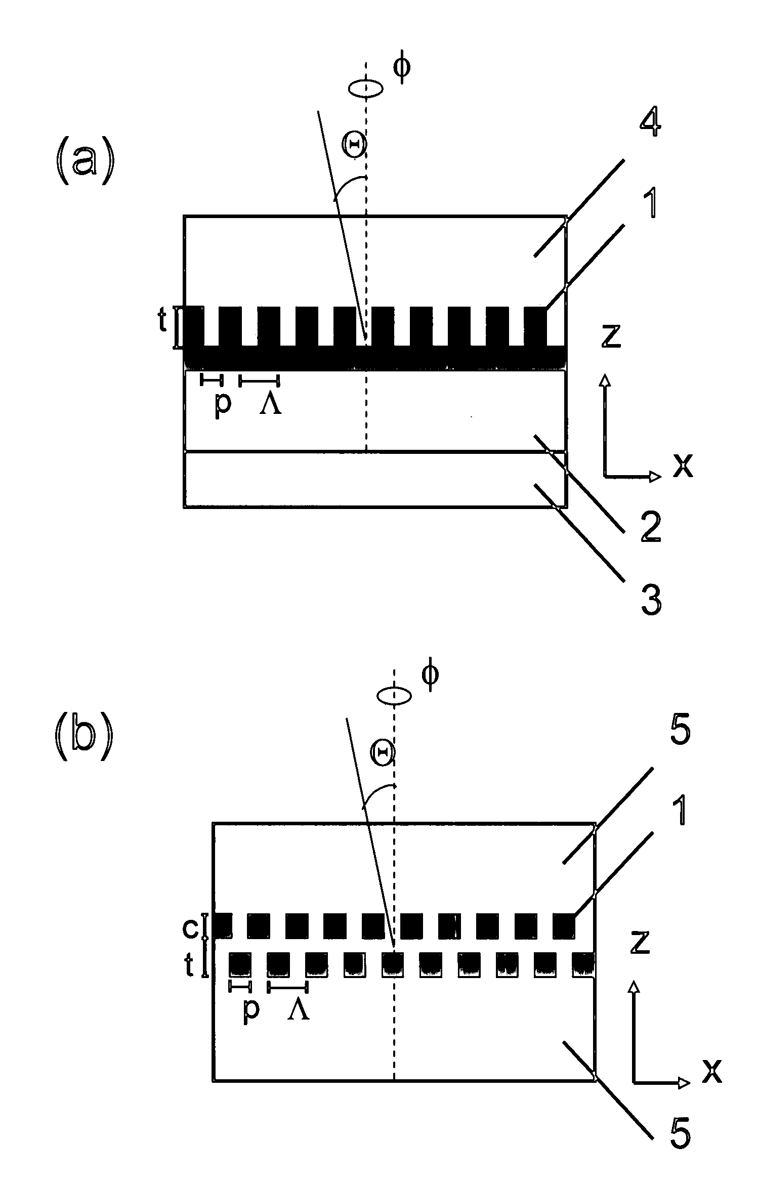
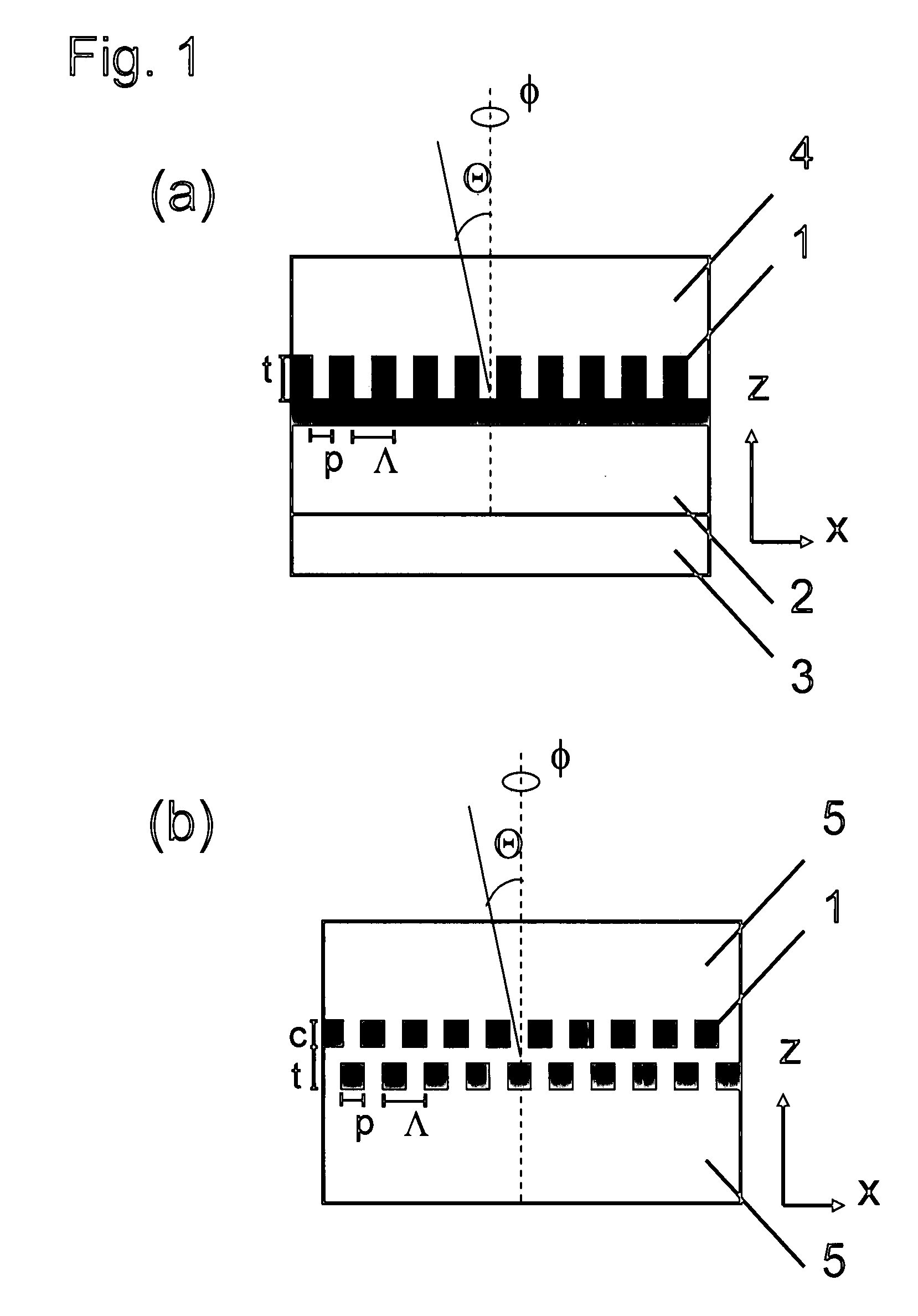
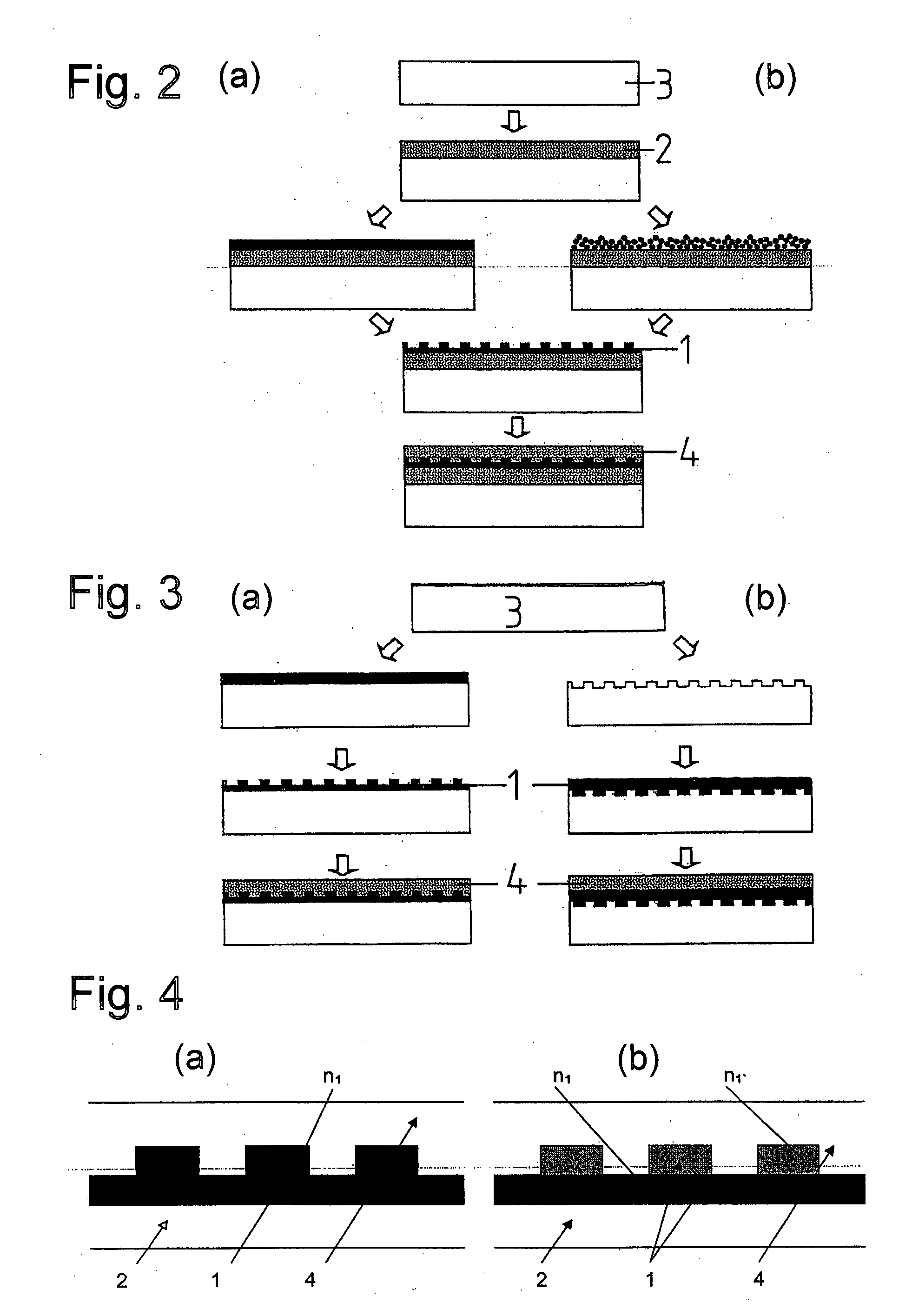
[0108]A first layer was deposited by curtain coating on a transparent PET substrate with a thickness of about 200 μm. The employed solution had a composition as described in table 4. The surface modified SiO2 is obtained according to example 1 of EP 1655348. Next, a second layer including polymer particles was curtain coated in a second coating step from a solution according to table 5. All coating steps took place in a continuous roll-to-roll process using a curtain coating machine. Next, a linear grating structure with a period of 1050 nm, a grating depth of 200 nm and a rectangular grating profile was hot embossed in the second layer at 80° C. Viewed at an angle of Θ=50° the obtained ZOF shows a pronounced color change upon rotation by 90°.

TABLE 4First layer (Low refractive index, porous)componentamount [g / m2]Surface modified SiO221.052Polyvinyl alcohol, Mowiol 40-88, Omya4.928AG, SwitzerlandHardener, Boric acid, Schweizerhalle0.8Chemie AG, Switzerlandtotal (solid)26.78Water157.3...


PUM


Abstract

A Zero-order diffractive filter comprising a first layer (1) with a periodic diffractive microstructure, forming a waveguide, and at least one adjacent second layer (2, 4, 5), wherein said first layer (1) has a refractive index that is higher than the refractive index of said second layer (2, 4, 5) by at least 0.2. At least one of said second layers (2, 4, 5) is a porous layer comprising nanopores. The period Λ of the diffractive microstructure is between 100 nm and 3000 nm.

Description

CROSS REFERENCE TO RELATED APPLICATIONS[0001]This application is a continuation-in-part application under §1.53(b) of prior application Ser. No. 11 / 827,143 filed Jul. 10, 2007, entitled ZERO—ORDER DIFFRACTIVE FILTER; which claimed priority under 35 USC §119(a)-(d) to European Application No. 06 015757 filed Jul. 28, 2006, the whole of which are each hereby incorporated herein by reference. Priority to each of these applications is herein claimed.TECHNICAL FIELD[0002]The present invention relates to Zero-order Diffractive filters (ZOF), to methods of manufacturing Zero-order Diffractive filters, to the use of such ZOFs and to the use of specific materials for manufacturing ZOFs.STATE OF THE ART[0003]Zero-order diffractive filters, also called resonant gratings, are well known, and described e.g. in D. Rosenblatt et al, “Resonant Grating Waveguide Structures” IEEE Journal of Quantum Electronics 33, 1997, p. 2038-2059 and M. T. Gale, “Zero-Order Grating Microstructures” in R. L. van Re...

Claims


Application Information

Patent Timeline
IPC IPC(8): G02B27/42G02B5/18B05D5/06
CPCB82Y20/00G02B5/1809G02B2207/101G02B6/124G02B5/1857G03H1/00
Inventor WALTER, HARALDGUGLER, GILBERTSTUCK, ALEXANDERBEER, ROBERTPAUCHARD, MARC
Owner CSEM CENT SUISSE DELECTRONIQUE & DE MICROTECHNIQUE SA RECH & DEV
Why Eureka
Try Eureka