Inset panel fastener

a technology for inset panels and fasteners, which is applied in the direction of fastening means, securing devices, screws, etc., can solve the problems of insufficient strength of inset panel fasteners made of plastic, and insufficient strength of inset panel fasteners. , to achieve the effect of high strength, easy use and low manufacturing cos

Active Publication Date: 2008-09-18
NMC GROUP
View PDF15 Cites 22 Cited by
  • Summary
  • Abstract
  • Description
  • Claims
  • Application Information

AI Technical Summary

Benefits of technology

[0018]It is a principal object of the present invention to provide an improved inset panel fastener which provides high strength.
[0019]It is another object of the present invention to provide an inset panel fastener which is lighter than comparable inset panel fasteners.
[0020]It is still another object of the present invention to provide an inset panel fastener which is inexpensive to manufacture and easy to use.

Problems solved by technology

However, adhesives and potting materials typically do not bond to an all metal material, such as titanium, as well as to a plastic material.
All metal fasteners are also heavy and expensive.
Meanwhile, inset panel fasteners made of plastic suffer from disadvantages of their own.
Unfortunately, these plastic inset panel fasteners suffer from several disadvantages.
However, threads made of plastic are typically not acceptable as locking threads where repeated engagement and disengagement may be encountered.
This interference provides the desired “locking action” caused by a large increase in friction.
Unfortunately, the telescopic rotations of the male threads against the plastic female threads of a plastic female fastener element causes the locking mechanism to wear down after only a few engagements and disengagements.
Once the locking mechanism has worn down, the locking threads are no longer capable of “locking” the male threads to the female threads making unwanted disengagement an unacceptable possibility.
Accordingly, inset panel fasteners having plastic threads have not be adopted in industry where a locking feature is required.
Unfortunately, these constructions are still undesirably heavier than all plastic constructions.

Method used


Image

  • Inset panel fastener
  • Inset panel fastener
  • Inset panel fastener

Examples


Embodiment Construction

[0027]While the present invention is susceptible of embodiment in various forms, as shown in the drawings, hereinafter will be described the presently preferred embodiments of the invention with the understanding that the present disclosure is to be considered as an exemplification of the invention, and it is not intended to limit the invention to the specific embodiments illustrated.

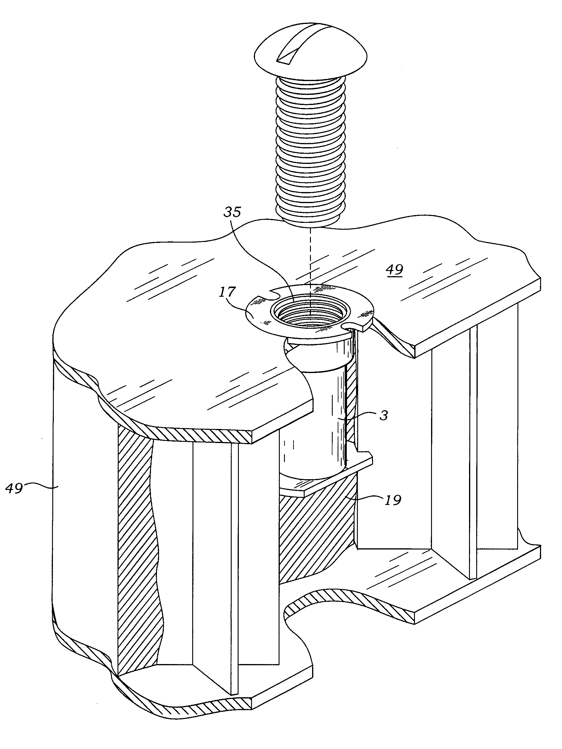
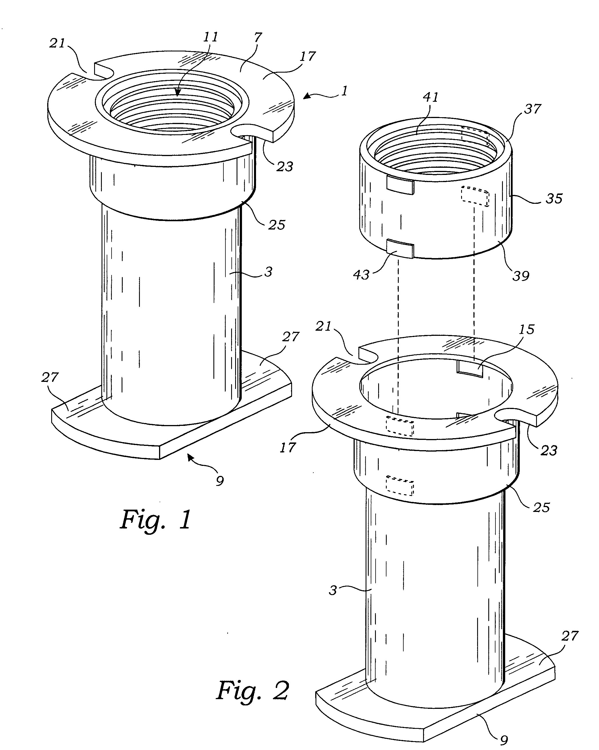
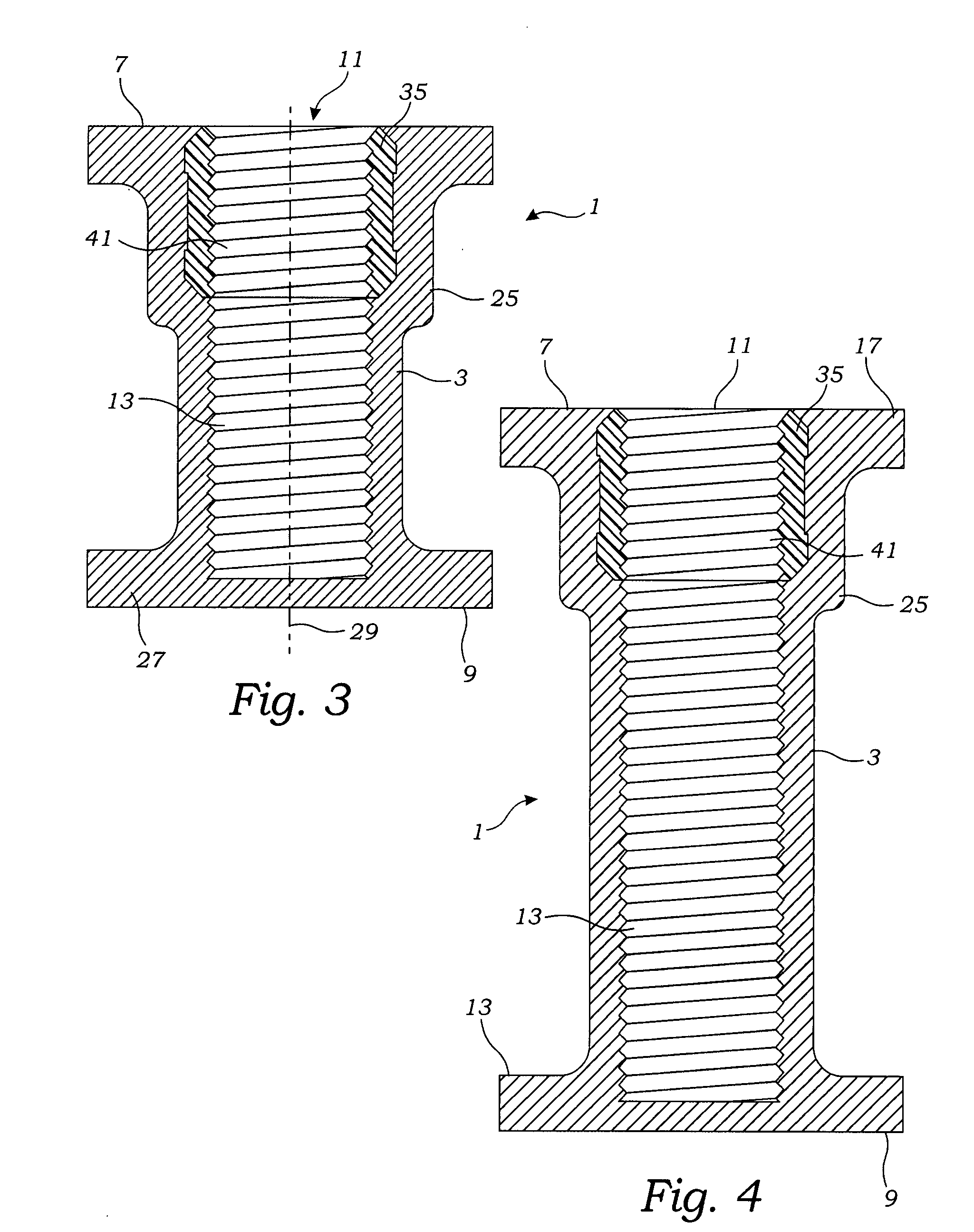
[0028]With reference to FIGS. 1-5, the inset panel fastener 1 of the present invention includes a plastic body 3 and metal female fastener 35 referred to herein as a nut. Cavities formed in honeycomb sandwich panels for receipt of an inset panel fastener are typically round and formed by a drill. Accordingly, the plastic body 3 of the inset panel fastener 1 preferably has a cylindrical barrel shape, and a top proximal extremity 7 and bottom distal extremity 9. The plastic body 3 further includes a central vertically extending bore centrally aligned with the inset panel fastener's longitudinal axis 29. T...


PUM


Abstract

An inset panel fastener is provided primarily for honeycomb substrates, such as those employed in the aircraft industry. The inset panel fastener includes a plastic body portion and a metal female threaded nut positioned within the body. The body includes a cylindrical barrel shape having a top and a bottom. A bore extends through the body from the top to form an opening for receipt of a male fastener. The metal nut has locking threads and is positioned in body's bore at the body's top proximal extremity. The body further includes non-locking plastic female threads integrally formed into said body's bore. The plastic female threads have the same diameter as the metal threads and are immediately adjacent to the metal threads so as to form continuous threads for permitting receipt of a male threaded fastener. The metal female threads are locking threads to provide a locking action for locking a male fastener to the inset panel fastener. Meanwhile, the plastic female threads provide primary load bearing capabilities for the inset panel fastener.

Description

BACKGROUND OF THE INVENTION[0001]The present invention relates to mounts and fasteners. More specifically, the present invention relates to inset panel fasteners which are particularly useful within the aircraft industry.[0002]Many types of mounting devices have been developed for holding one or more objects to a support surface. For example, inset-type fasteners are generally anchored into a structure and include an engagement portion, such as the male or female threads of a screw, for securing objects to the structure. Inset fasteners are particularly advantageous when a strong connection between the structure and object cannot be readily obtained through use of a surface mounted structure.[0003]Sandwich panels are used extensively in the aircraft and marine industries. These sandwich panels typically are made of fiberglass or similar material formed in a honeycomb structure. The honeycomb structure is then typically sandwiched between outer layers of aluminum panels or the like. ...

Claims


Application Information

Patent Timeline
Patent Type & Authority Applications(United States)
IPC IPC(8): F16B1/00F16B39/00
CPCF16B5/0208F16B39/30F16B37/12Y10S411/903
Inventor STEPHEN, ROBERT
Owner NMC GROUP
Why Eureka
Try Eureka