Centrifugal impeller, fan apparatus, and electronic device

a centrifugal impeller and fan technology, applied in the direction of machines/engines, liquid fuel engines, instruments, etc., can solve the problems of air blowing performance degradation and air flow performance degradation, and achieve the reduction of the flow path resistance of the air stream in the rotational axis direction, the effect of increasing the flow rate of the air stream discharged from the centrifugal impeller in the centrifugal direction

Inactive Publication Date: 2008-09-18
SONY CORP
View PDF9 Cites 19 Cited by
  • Summary
  • Abstract
  • Description
  • Claims
  • Application Information

AI Technical Summary

Benefits of technology

[0012]According to this embodiment, the plurality of second centrifugal blades are spaced apart from the boss portion, so there is a space between the boss portion and the second centrifugal blades. Accordingly, air stream in a rotational axis direction generated owing to the rotation of the centrifugal impeller is likely to be sucked. That is, flow path resistance of the air stream in the rotational axis direction is decreased. In addition, noise due to the flow path resistance of the air stream can be suppressed.
[0013]In addition, the air stream in the rotational axis direction sucked by the centrifugal impeller is accelerated in the vicinity of the boss portion by the plurality of rotating first centrifugal blades in the centrifugal direction. Accordingly, the air stream in the vicinity of the boss portion of the centrifugal impeller can be accelerated in the centrifugal direction. Thus, flow rate of the air stream discharged from the centrifugal impeller in the centrifugal direction can be increased.

Problems solved by technology

As a result, flow path resistance is increased, and thus air blow performances are deteriorated.
Also in this case, air blow performances are deteriorated.

Method used


Image

  • Centrifugal impeller, fan apparatus, and electronic device
  • Centrifugal impeller, fan apparatus, and electronic device
  • Centrifugal impeller, fan apparatus, and electronic device

Examples


first embodiment

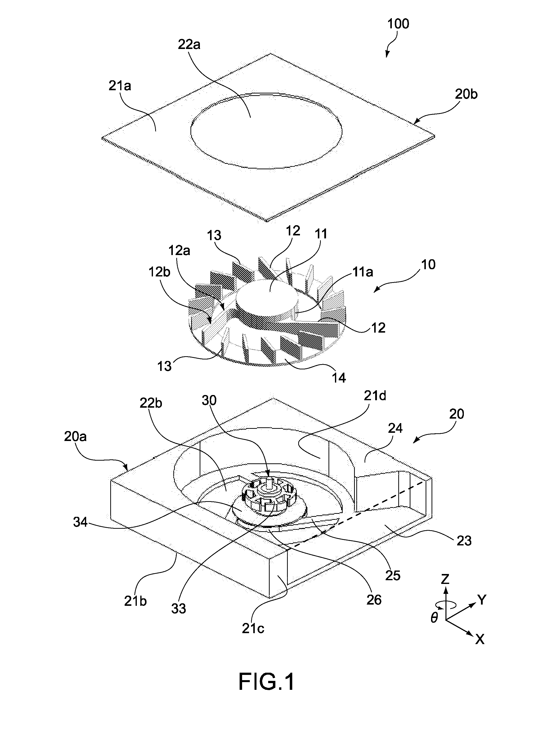
[0044]A first embodiment of the present invention will be described. FIG. 1 is an exploded perspective view showing a fan apparatus according to this embodiment.

[0045]FIG. 2 is a cross-sectional view showing an inner structure of the fan apparatus of FIG. 1, denoted by reference numeral 100.

[0046]As shown in FIG. 1, the fan apparatus 100 includes a centrifugal impeller (propeller for a centrifugal fan) 10, a case 20, and a stator 30.

[0047]The centrifugal impeller 10 includes, at a center thereof, a substantially-cylindrical boss portion 11 capable of rotating in a θ direction about an axis in a Z direction. The boss portion 11 is provided with, at an outer circumferential surface 11a, a plurality of centrifugal long blades (first centrifugal blades) 12.

[0048]The plurality of centrifugal long blades 12 extend from the outer circumferential surface 11a in a centrifugal direction by predetermined angles. The plurality of centrifugal long blades 12 are arranged to have substantially the...

second embodiment

[0061]Subsequently, a second embodiment of the present invention will be described. Hereinafter, the description of members, functions, and the like similar to those of the fan apparatus 100 according to the first embodiment will be simplified and omitted. Members, functions, and the like different from those of the fan apparatus 100 will mainly be described.

[0062]FIG. 3 is an exploded perspective view of a fan apparatus according to this embodiment.

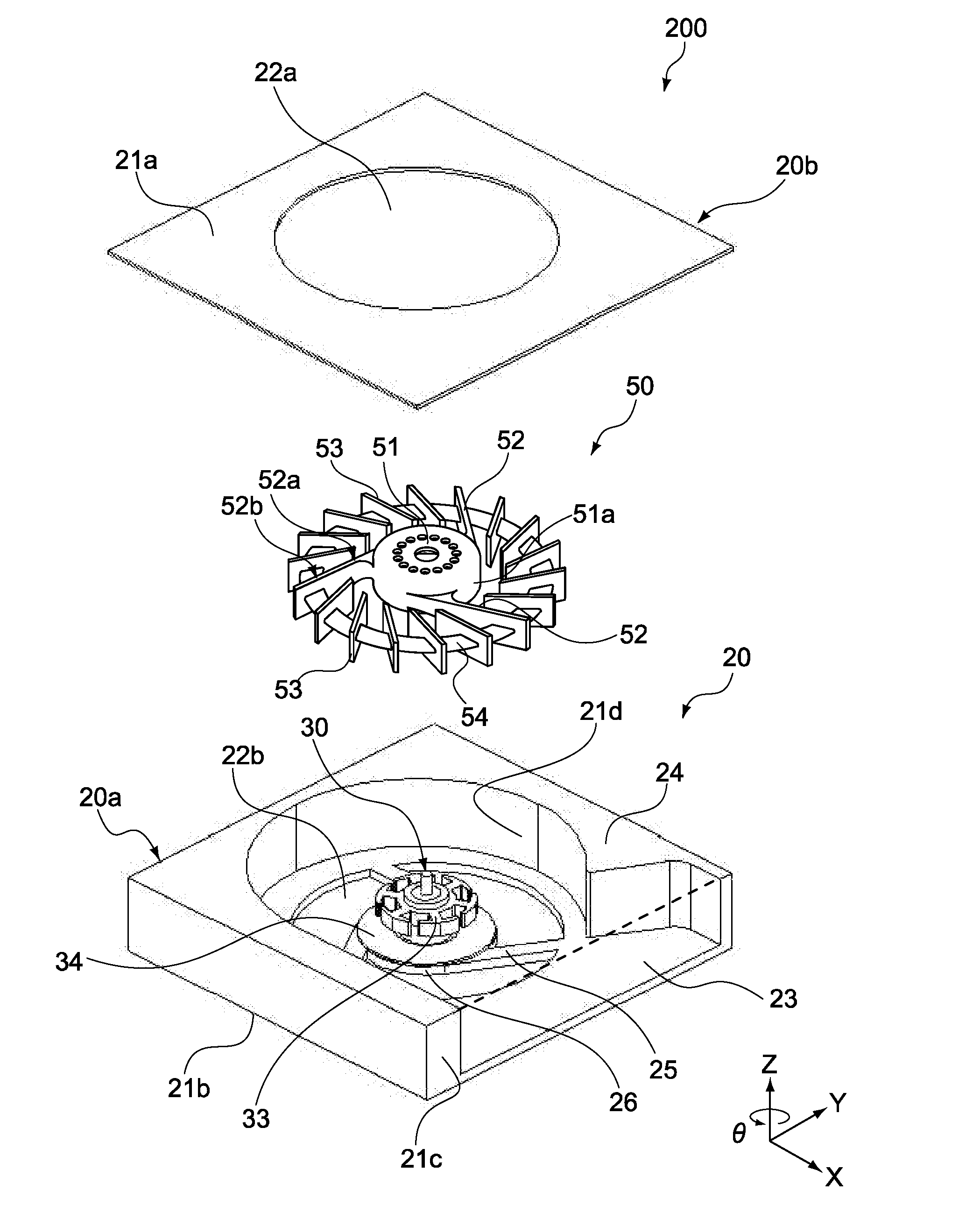
[0063]The fan apparatus, denoted by reference numeral 200, includes a centrifugal impeller 50, the case 20, and the stator 30.

[0064]Among those, the centrifugal impeller 50 is different from the centrifugal impeller 10 described above. So the centrifugal impeller 50 will mainly be described in this embodiment.

[0065]FIG. 4 is a perspective view showing the centrifugal impeller 50. FIG. 5 is a front view thereof. FIG. 6 is a rear view thereof. FIG. 7 is a top view thereof. FIG. 8 is a bottom view thereof. FIG. 9 is a right-side view thereo...

third embodiment

[0070]Subsequently, a third embodiment of the present invention will be described. FIG. 11 is a cross-sectional view of a fan apparatus according to the third embodiment.

[0071]In this embodiment, a centrifugal long blade 62 includes, at an inner circumferential side thereof, a second blade area 62a, and, at an outer circumferential side thereof, a first blade area 62b. The centrifugal long blade 62 is structured such that the second blade area 62a has a width w1 in the rotational axis direction larger than a width w2 of the first blade area 62b in the rotational axis direction. For example, the width w1 of the centrifugal long blade 62 at the inner circumferential side is substantially the same as a distance d1 between the upper surface 21a and the lower surface 21b of the case 20. In other words, an upper edge portion 62a-1 of the second blade area 62a of the centrifugal long blade 62 and the upper surface 21a of the case 20 are substantially in a same plane. Further, a lower edge ...


PUM


Abstract

There is provided a centrifugal impeller that includes a boss portion, a plurality of first centrifugal blades, a plurality of second centrifugal blades, and a coupling portion. The boss portion is capable of rotating. The plurality of first centrifugal blades are provided to the boss portion such that the plurality of first centrifugal blades extend from the boss portion. The plurality of second centrifugal blades are provided around the boss portion such that the plurality of second centrifugal blades are spaced apart from the boss portion. The coupling portion couples the plurality of first centrifugal blades and the plurality of second centrifugal blades.

Description

CROSS REFERENCES TO RELATED APPLICATIONS[0001]The present invention contains subject matter related to Japanese Patent Application JP 2007-067779 filed in the Japanese Patent Office on Mar. 16, 2007, the entire contents of which being incorporated herein by reference.BACKGROUND OF THE INVENTION[0002]1. Field of the Invention[0003]The present invention relates to a centrifugal impeller that generates wind in a centrifugal direction, a fan apparatus that employs the centrifugal impeller, and an electronic device that is mounted with the fan apparatus.[0004]2. Description of the Related Art[0005]As PCs (Personal Computers) are enhanced in performances, heat generators such as ICs (Integrated Circuits) generate heat more, which has been problematic. In view of this, various technologies for releasing heat have been proposed, and products employing such technologies have been manufactured. One method of releasing heat includes intentionally eliminating heated air in a casing of a PC by u...

Claims


Application Information

Patent Timeline
Patent Type & Authority Applications(United States)
IPC IPC(8): F03D11/00
CPCF04D25/0613F04D29/384F04D29/329F04D29/327F04D29/281F04D29/30F04D17/162G06F1/20H05K7/20
Inventor FUJIEDA, TADAOMI
Owner SONY CORP
Why Eureka
Try Eureka