High efficiency cooling fan

a high-efficiency, fan technology, applied in the direction of liquid fuel engines, marine propulsion, vessel construction, etc., can solve the problems of reducing life span, increasing power to operate, generating more noise, etc., to achieve maximum performance and range, minimize flow weakness, and maximize efficiency

Active Publication Date: 2008-09-18
BASCOM HUNTER TECH INC
View PDF23 Cites 100 Cited by
  • Summary
  • Abstract
  • Description
  • Claims
  • Application Information

AI Technical Summary

Benefits of technology

[0013]The impeller and the outlet guide vane assembly may be aerodynamically designed using three-dimensional computational fluid dynamics to ensure that flow weakness is minimized and efficiency is maximized. For example, the impeller blades and guide vanes may be designed using numerous tailored airfoil segments, and bow and lean may be incorporated into the blades and vanes in order to achieve maximum performance and range. In addition, the leading edge of the guide vanes may be swept aft to reduce the amount of noise generated by the fan.
[0014]Bow may be incorporated into the guide vanes to help balance the aerodynamic loading across the vanes in the spanwise direction. Increasing bow in this direction reduces the aerodynamic loading of the airfoil segments near the end walls and results in increased loading of the airfoil segments near the midspan. Bow also tends to energize the end wall boundary layers, making them less susceptible to separation. The outlet guide vanes may comprise a leading edge that is especially curved near the hub and the tip. The trailing edge may be bowed in the same direction and to a greater degree than the leading edge.

Problems solved by technology

These motors usually require increased power to operate, generate more noise and have reduced life spans.
Fan inefficiencies may result from virtually any choice made during the design process, from architecture selection through the detailed design of the flowpath surfaces, the impeller blades and the guide vanes.
In prior art cooling fans in which the flow near the midspan of the blades or vanes is weak, however, increasing the bow and lean angles may be detrimental since it would increase the aerodynamic loading near the midspan.
Because the flow near the midspan is already weak, additional loading from increased bow would lead to increased flow separation and poorer performance.

Method used


Image

  • High efficiency cooling fan
  • High efficiency cooling fan
  • High efficiency cooling fan

Examples


Embodiment Construction

[0028]The present invention is applicable to a variety of air movers. However, for purposes of brevity it will be described in the context of an exemplary vane-axial cooling fan. Nevertheless, the person of ordinary skill in the art will readily appreciate how the teachings of the present invention can be applied to other types of air movers. Therefore, the following description should not be construed to limit the scope of the present invention in any manner.

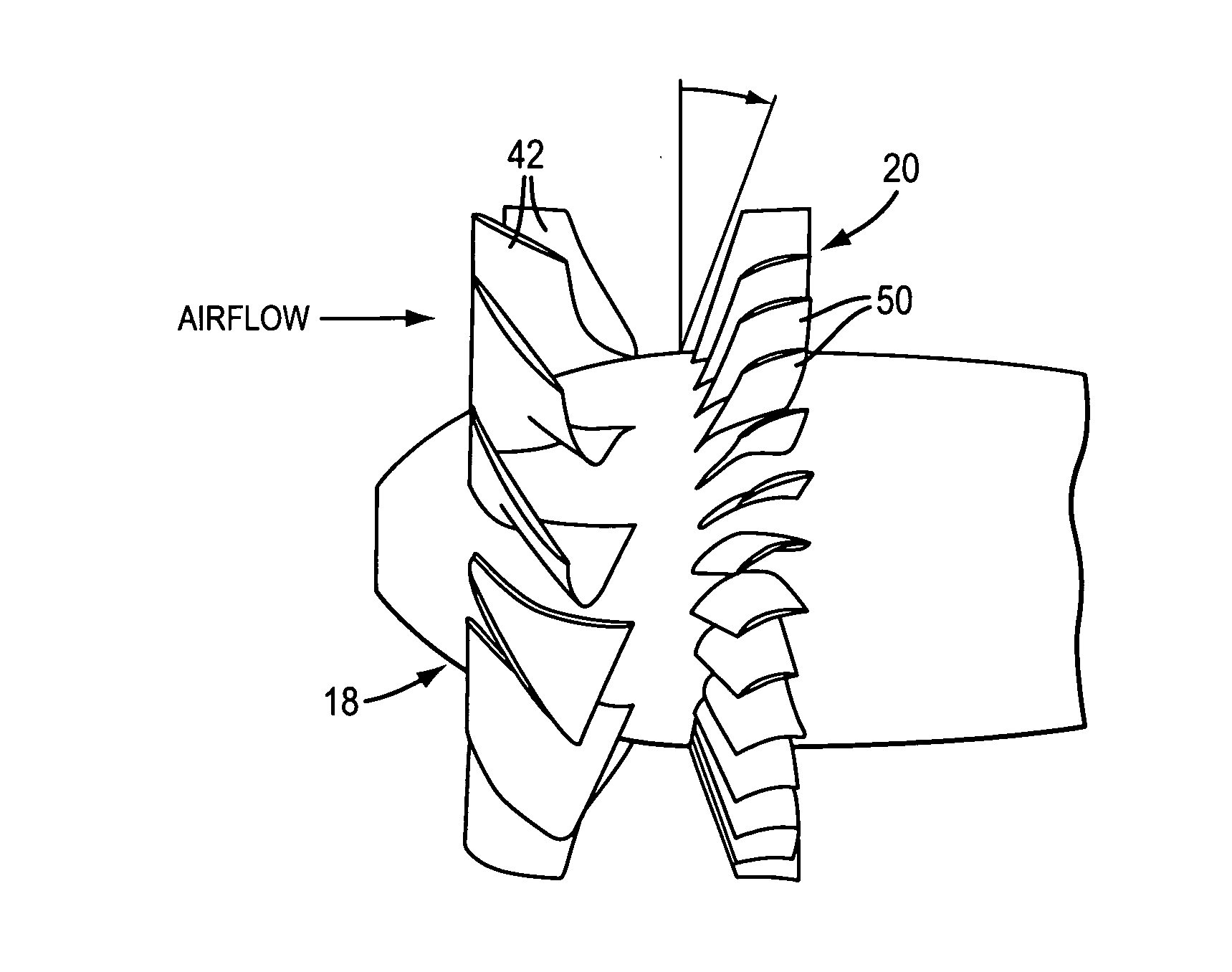
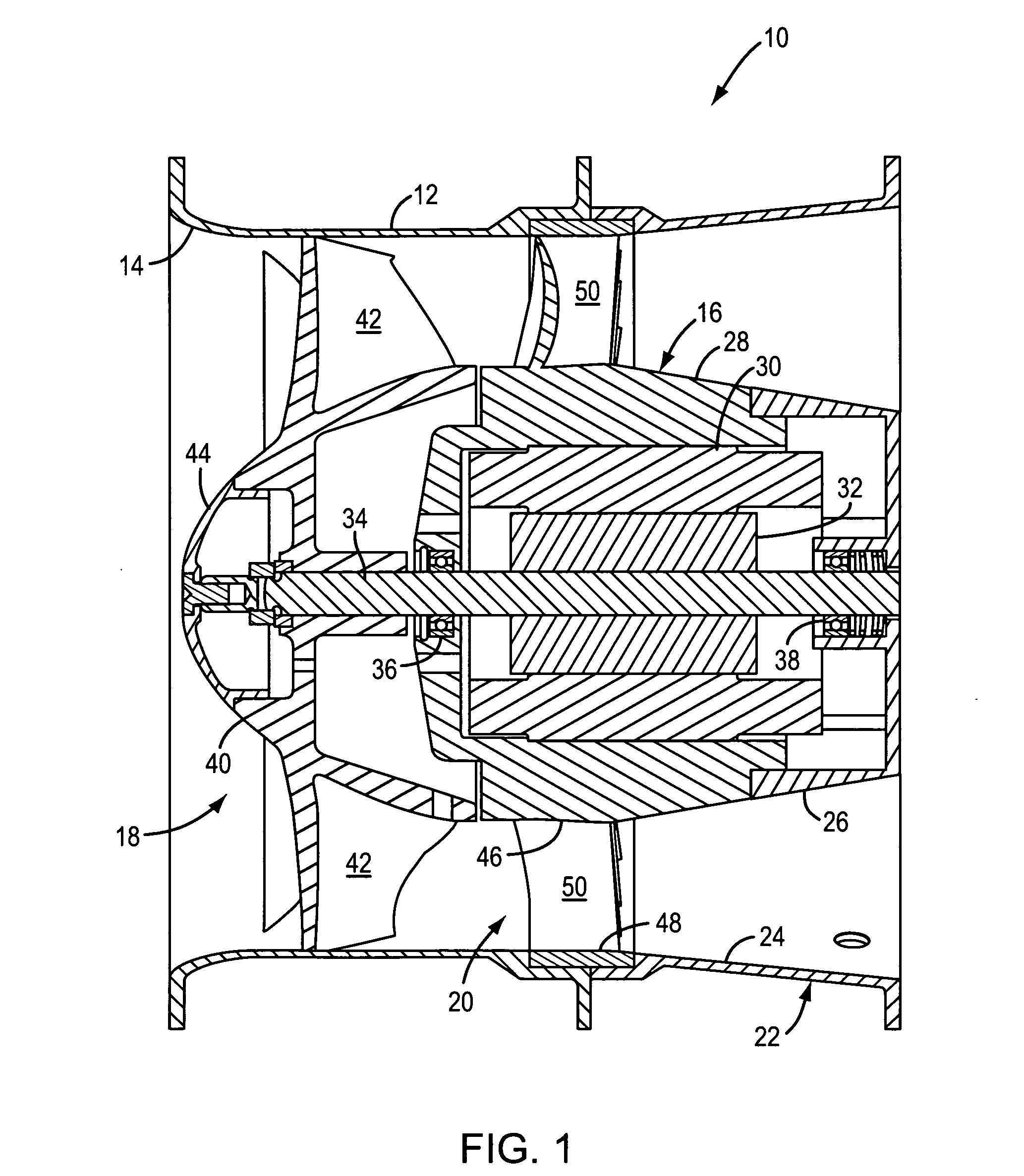
[0029]Referring to FIG. 1, an exemplary vane axial cooling fan 10 is shown to comprise a fan housing 12 which includes a converging inlet 14, a motor 16 which is supported in the fan housing, an impeller 18 which is driven by the motor, and an outlet guide vane assembly 20 which extends radially between the motor and the fan housing. The cooling fan 10 may also include a diffuser section 22 which is located downstream of the outlet guide vane assembly and which includes a diffuser tube 24 that is connected to or formed integral...


PUM


Abstract

A cooling fan includes an impeller which comprises a plurality of radially extending blades, each of which includes a blade hub, a blade tip and a blade midspan approximately midway between the hub and the tip. In addition, each blade includes a camber of between about 60° and 90° at the blade hub, between about 15° and 40° at the blade midspan and between about 15° and 40° at the blade tip.

Description

[0001]This application is based on and claims the benefit of U.S. Provisional Patent Application No. 60 / 905,248, which was filed on Mar. 5, 2007.BACKGROUND OF THE INVENTION[0002]This present invention relates to a high efficiency, high work coefficient fan which can be used, for example, in electronics cooling applications.[0003]Many prior art cooling fans include a motor-driven impeller which propels a stream of air through a fan housing. These fans may also comprise an outlet guide vane assembly which is positioned downstream of the impeller to both de-swirl and increase the static pressure of the air, and a diffuser section which is located downstream of the outlet guide vane assembly to decelerate and thereby further increase the static pressure of the air.[0004]The impeller and the outlet guide vane assembly each include a plurality of radially extending blades or vanes. The shape of each blade or vane can be defined by the values of camber, chord and stagger for each of a plur...

Claims


Application Information

Patent Timeline
Patent Type & Authority Applications(United States)
IPC IPC(8): F01D5/14F04D29/38
CPCF04D25/0606F04D29/384
Inventor DECKER, JOHNBALAN, CHELLAPPA
Owner BASCOM HUNTER TECH INC
Why Eureka
Try Eureka