Method and Apparatus for Manufacturing Carbon Nano Tube

a carbon nano and manufacturing method technology, applied in the direction of carbonsing rags, mechanical vibration separation, chemical/physical/physico-chemical processes, etc., can solve the problem of non-uniform metal catalyst production, temperature of reaction gas that is not spatially uniform, and limitation of carbon nanotube manufacturing having a uniform property, etc. problem, to achieve the effect of uniform property and high purity

Inactive Publication Date: 2008-09-18
KOREA ADVANCED INST OF SCI & TECH
View PDF3 Cites 10 Cited by
  • Summary
  • Abstract
  • Description
  • Claims
  • Application Information

AI Technical Summary

Benefits of technology

[0015]Furthermore, according to the present invention, instead of performing the metal catalyst cluster generation process and the carbon nano tube growth process simultaneously, the process of generating metal catalyst clusters and the process of growing carbon nano tubes can be separated and independently performed. Therefore, a carbon nano tube having a uniform property and high purity can be produced.

Problems solved by technology

This means that the temperature of the reaction gas is not spatially uniform.
As described above, since the process of manufacturing a carbon nano tube according to a method for heating reaction gas through heat transfer due to the temperature gradient, such as the HiPco process, is premised on inevitable non-uniformity of the reaction gas temperature, non-uniform metal catalyst is produced due to the non-uniform temperature distribution in the reactor.
There is a limitation on the manufacture of a carbon nano tube having a uniform property.

Method used


Image

  • Method and Apparatus for Manufacturing Carbon Nano Tube
  • Method and Apparatus for Manufacturing Carbon Nano Tube
  • Method and Apparatus for Manufacturing Carbon Nano Tube

Examples


Embodiment Construction

[0033]FIG. 3 illustrates a principle of manufacturing a carbon nano tube according to the present invention. A reaction vessel 10 shown in FIG. 3 (a) is filled with prefilled reactions gas (a mixed gas of Fe(CO)5 and CO) for a carbon nano tube at a predetermined ratio. An external force is applied to move a piston 20 in a direction of an arrow shown in FIG. 3 (a) such that the reaction gas in the closed reaction vessel 10 can be compressed. This adiabatic compression is an isentropic process by which the temperature of the reaction gas is raised. According to the isentropic relationship expressed in the following well-known equation (1), the temperature of the reaction gas is raised.

T / To=(V / Vo)−(r−1)=(p / po)(r−1) / r,  (1)

[0034]where T, V and p are temperature, volume and pressure of the reaction gas, respectively; r is a heat insulation coefficient (in such a case, approximately 1.4), and a subscript “o” means an initial value. As the volume of the reaction gas is reduced due to the c...


PUM

PropertyMeasurementUnit
temperatureaaaaaaaaaa
heataaaaaaaaaa
pressureaaaaaaaaaa

Abstract

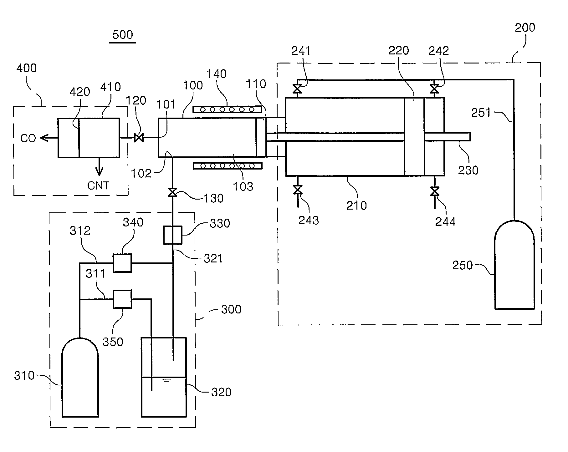
The present invention relates to a method and apparatus for manufacturing a carbon nano tube, and more particularly, to a method and apparatus for manufacturing a carbon nano tube by which a carbon nano tube having a uniform property and high purity can be manufactured by uniformly raising a temperature of reaction gas, which includes a gaseous transition metal catalyst precursor compound and gaseous carbon compound contained in a hermetically closed reaction space, to the Boudouard reaction temperature. The method for manufacturing a carbon nano tube according to the present invention comprises the steps of preparing a reaction vessel including a substantially hermetic and compressible reaction space; supplying the reaction space with carbon nano tube reaction gas containing a gaseous carbon compound and a gaseous transition metal catalyst precursor compound; and compressing the reaction gas in the reaction space until a temperature of the carbon nano tube reaction gas supplied to the reaction space reaches a temperature equal to or greater than a minimum starting temperature of the Boudouard reaction and a temperature at which the transition metal catalyst precursor compound is thermally decomposed, thereby producing gas with carbon nano tube products suspended therein.

Description

TECHNICAL FIELD[0001]The present invention relates to a method and apparatus for manufacturing a carbon nano tube, and more particularly, to a method and apparatus for manufacturing a carbon nano tube by which a carbon nano tube having a uniform property and high purity can be manufactured by uniformly raising a temperature of reaction gas, which includes a gaseous transition metal catalyst precursor compound and gaseous carbon compound contained in a hermetically closed reaction space, to the Boudouard reaction temperature.BACKGROUND ART[0002]In general, a carbon nano tube (CNT) is one of the four known forms of solid carbon, the other three being diamond, C60, and graphite, and is in a tabular form. CNTs have many properties that can potentially be exploited for various worthwhile purposes.[0003]The general principle of CNT formation is well known in the art. In general, CNT is produced when carbon-bearing gas molecules such as carbon monoxide (CO) collide against a surface of a m...

Claims


Application Information

Patent Timeline
Patent Type & Authority Applications(United States)
IPC IPC(8): B82B3/00C01B31/00B01J19/00B06B1/00
CPCB82Y30/00C01B31/0233B82Y40/00C01B32/162B82B3/0004B82B3/0009
Inventor PARK, CHULCHANG, KEUN-SHIK
Owner KOREA ADVANCED INST OF SCI & TECH
Why Eureka
Try Eureka