
Diffusive plasma air treatment and material processing

a plasma and air treatment technology, applied in the field of diffuse plasma air treatment and material processing, can solve the problems of rapid increase of charge density, fast growth of avalanches, and transformation of streamers into arcs, and achieve more controllable and uniform properties, better efficiency, and plasma properties.

Inactive Publication Date: 2008-03-06
ALPHATECH INT
View PDF6 Cites 27 Cited by
  • Summary
  • Abstract
  • Description
  • Claims
  • Application Information

AI Technical Summary

Benefits of technology

[0014]In view of the aforesaid disadvantages present in the prior art and based on the principles as mentioned above, the method and device of the present invention provides a process of generating plasma with more controllable and uniform properties so that plasma properties can be optimized to achieve better efficiency while minimizing the generation of unwanted bi-product gases.
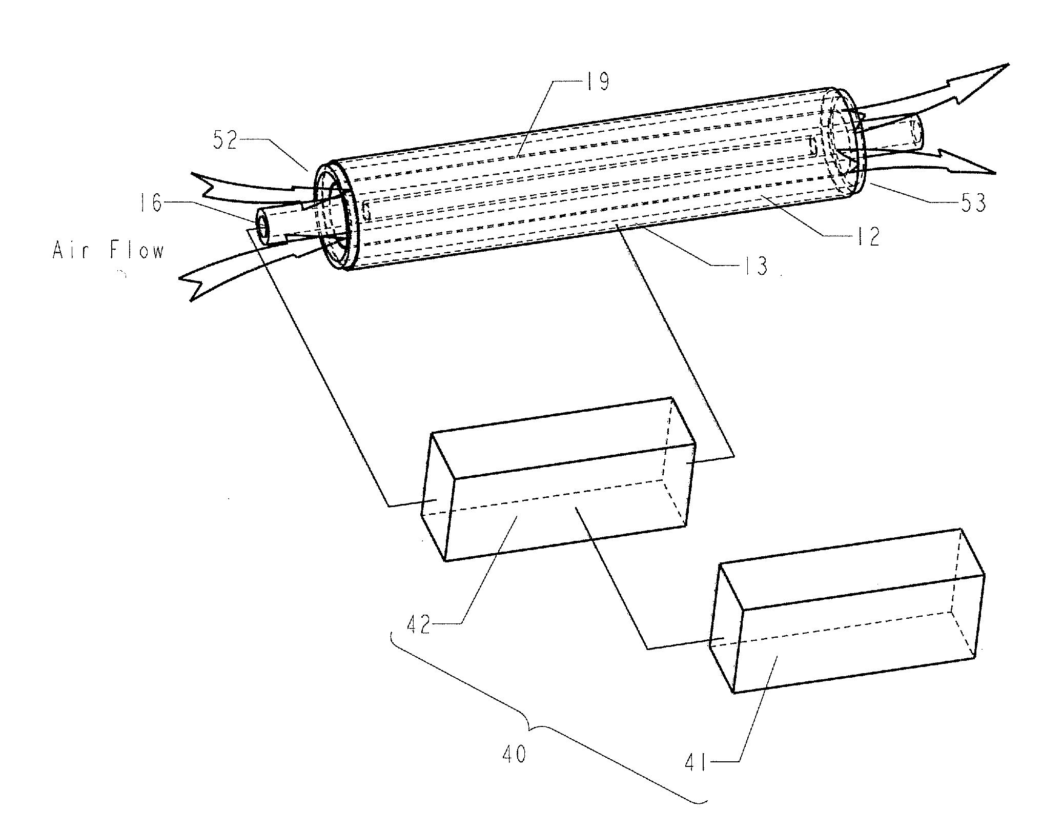
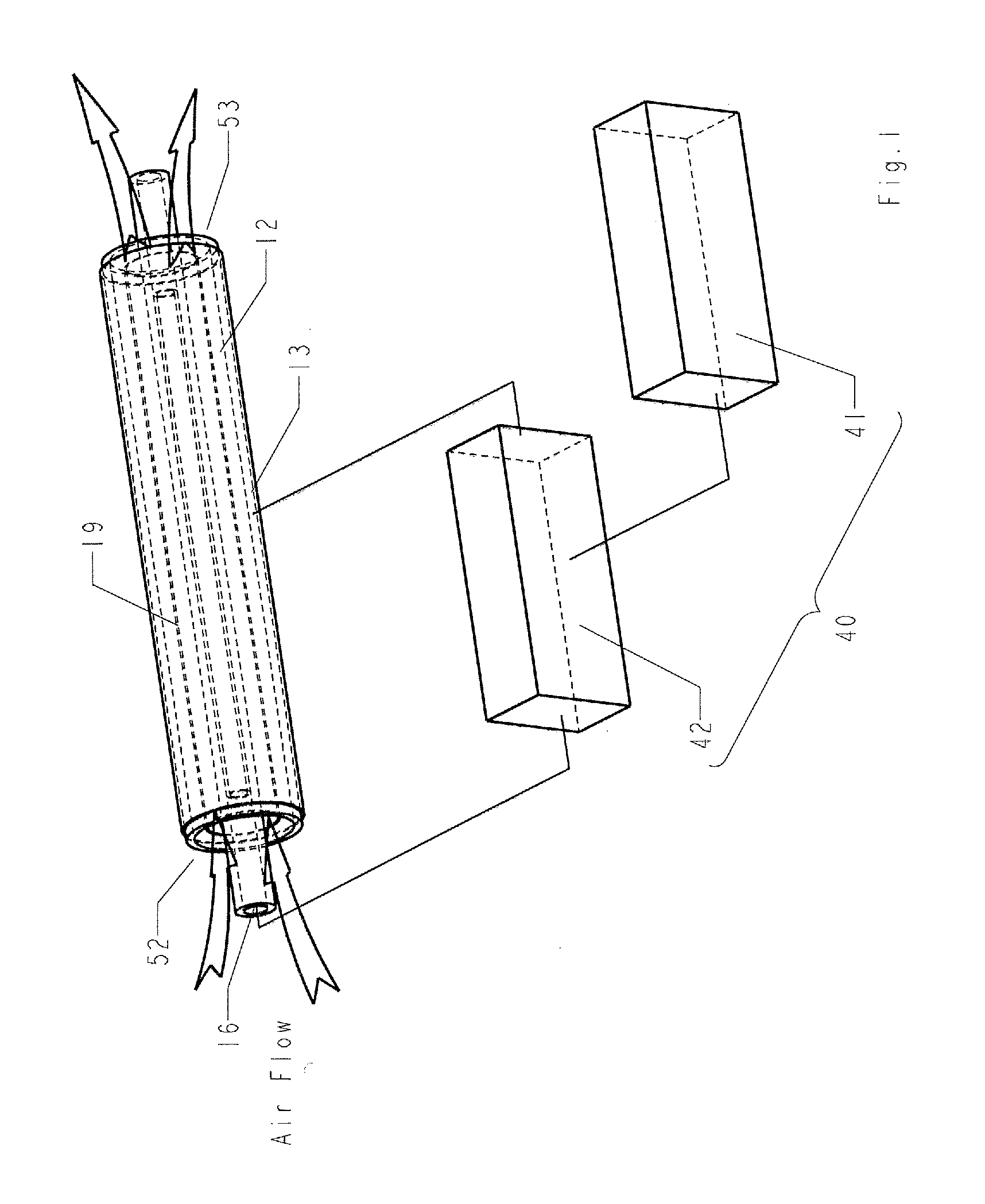
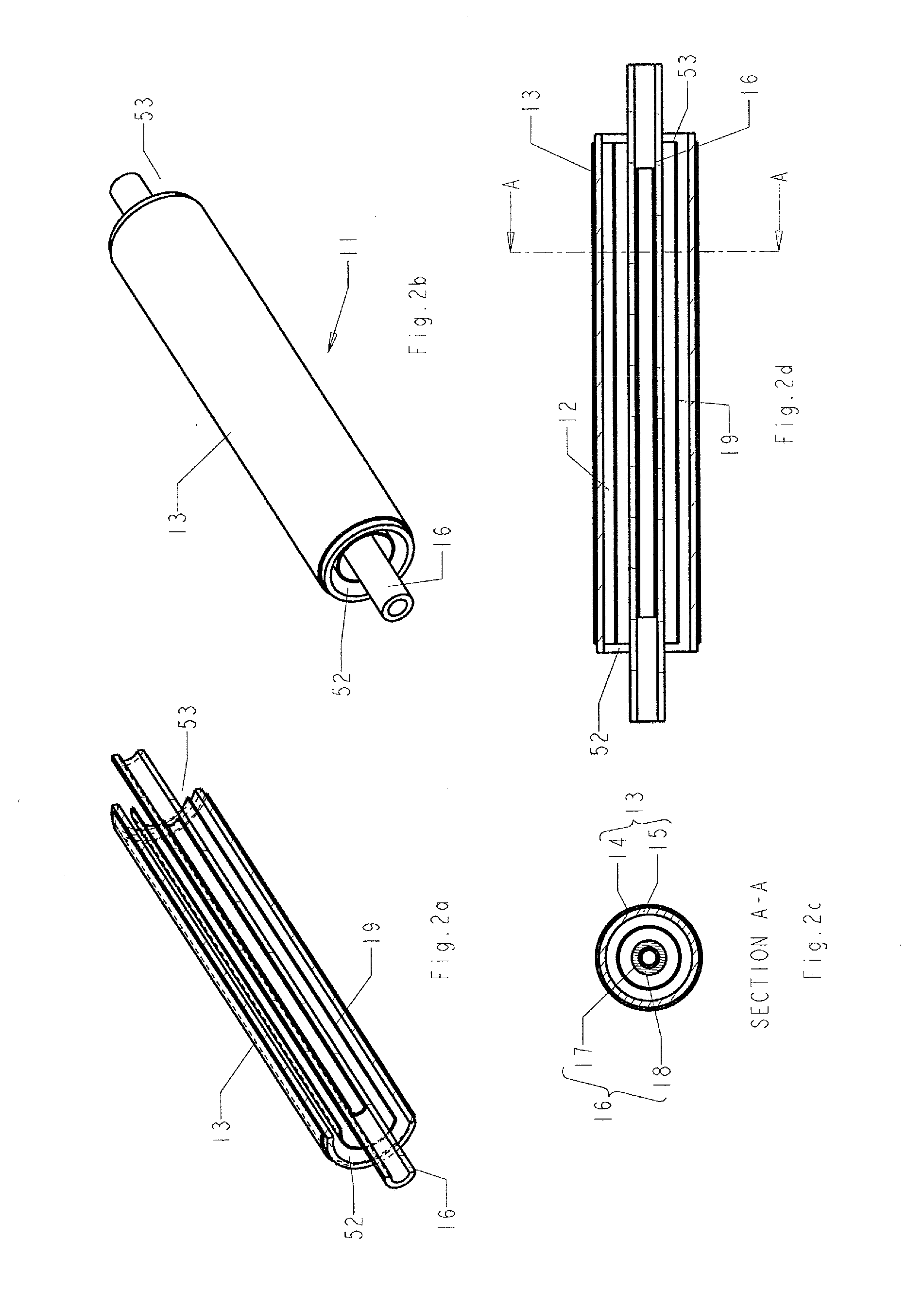
[0015]The diffusive plasma device is a novel method and device to create plasma for air treatment and material processing. The diffusive plasma device generally comprises a reactor with a diffuser placed in the reaction chamber space between the two insulated electrodes powered by an alternating current power source. The reactor creates discharges directly to the air within the reactor chamber. The diffuser allows plasma properties to be modified for higher efficiency while minimizing the generation of unwanted bi-product gases. By incorporating suitable catalytic materials with the diffuser, the reactor becomes a catalytic plasma reactor wherein the plasma environment provides enhanced catalytic actions. With the use of suitable filtering materials, the diffuser can also act as a filter.

Problems solved by technology

The formation of such a streamer or discharge filament, if unrestrained, leads to a rapid increase in charge density, fast growth of an avalanche, and the transformation of the streamer into an arc.
Therefore, the low charge mobility on the insulating or dielectric layer leads to self-arresting of the filaments and also limits their lateral extension, thereby allowing multiple filaments to form in close proximity to one another.
A typical plasma reactor for air treatment and material processing based on the above mentioned design principles generally suffer from unstable and variations in operation.
One of the commonly encountered problems is the generation of quasi-steady filaments, i.e., filaments that reoccur persistently at the same location.
While these filaments may not develop into arcs, their existence results in localized plasma generation and reduces the usefulness of the plasma for air treatment and material processing.
For instance, effective air treatment requires harmful contaminants in air to have an adequate ‘residence time’ within the reactor device.
Non-uniform plasma generation can reduce the treatment strength and thereby increase the required ‘residence time’ for treatment.
The formation of these quasi-steady filaments can also lead to a higher generation of some undesirable by-product gases.

Method used


Image

  • Diffusive plasma air treatment and material processing
  • Diffusive plasma air treatment and material processing
  • Diffusive plasma air treatment and material processing

Examples


Embodiment Construction

[0086]Reference will now be made in detail to a preferred embodiment of the invention, examples of which are also provided in the following description. Exemplary embodiments of the invention are described in detail, although it will be apparent to those skilled in the relevant art that some features that are not particularly important to an understanding of the invention may not be shown for the sake of clarity.

[0087]Furthermore, it should be understood that the invention is not limited to the precise embodiments described below and that various changes and modifications thereof may be effected by one skilled in the art without departing from the spirit or scope of the invention. For example, elements and / or features of different illustrative embodiments may be combined with each other and / or substituted for each other within the scope of this disclosure and appended claims.

[0088]In addition, improvements and modifications which may become apparent to persons of ordinary skill in t...


PUM

PropertyMeasurementUnit
voltageaaaaaaaaaa
distanceaaaaaaaaaa
voltageaaaaaaaaaa

Abstract

The Diffusive Plasma is for effective treatment of contaminated air and material processing. Air is purified and disinfected by passing through the diffusive plasma device which includes a reactor or a plurality of reactors arranged in parallel or series and is energized by a high voltage alternating current power supply. The diffuser, being electrically isolated, provides extra nucleation sites to initiate discharges. It serves to improve the generation of uniform and consistent plasma and to reduce the variation of discharge properties among the reactors. The addition of a diffuser, thereby, enhances the overall effectiveness of decomposing chemicals and destroying microbes to achieve high air treatment and material processing performance. The diffuser can be made of suitable filtering materials to additionally serve as a filter. By incorporating suitable catalytic materials with the diffuser, the reactor becomes a catalytic plasma reactor wherein the plasma environment provides enhanced catalytic functions. Effective plasma power deposition may be obtained by controlling the amplitude, waveform period and shape of the voltage applied to the electrodes of the reactor and hence the operation of the reactors with plasma discharged of selected conditions for optimizing the treatment and processing efficiency while minimizing the generation of unwanted bi-product gases. The present invention also relates to a method for effective air treatment and material processing.

Description

CROSS-REFERENCE TO RELATED APPLICATIONS[0001]This application claims priority from U.S. Provisional Patent Application No. 60 / 824,468, filed on Sep. 5, 2006, which is incorporated herein by reference in its entirety.TECHNICAL FIELD[0002]The present invention relates generally to the application of plasma for air treatment and material processing and more particularly pertains to a plasma device for air purification and disinfection. The present invention also relates to a method for generating controllable and uniform plasma to improve the performance of air treatment and material processing.BACKGROUND[0003]The following description of the background of the invention is provided to aid in understanding the invention, but is not admitted to describe or constitute prior art to the invention.[0004]Plasma is referred to as the ‘4th state of matter’, and is a partially ionized gas composed of freely moving ions, electrons, and neutral particles. While plasma is electrically neutral, it i...

Claims


Application Information

Patent Timeline
Patent Type & Authority Applications(United States)
IPC IPC(8): A61L9/16A61L9/00B01J19/00B01J19/12
CPCA61L9/22B03C2201/10B03C3/49B03C2201/08C01B13/11C01B2201/14C01B2201/22C01B2201/32C01B2201/34C01B2201/60C01B2201/90F24F2003/1635F24F2003/1682H05H1/24B03C3/41A61L2209/11F24F8/194F24F3/167F24F8/30F24F8/192H05H1/2406Y02A50/20H05H1/2437H05H1/2443H05H2245/15
Inventor TSUI, HERMAN YIK WAI
Owner ALPHATECH INT
Learn More