Lancet device

a technology of a piercing device and a tensioning spring, which is applied in the field of piercing devices, can solve the problems of cumbersome manual tensioning of the drive springs after piercing, large and heavy due to the electric motor, and the burden of the integrated electric motor, so as to reduce the noise of piercing, the effect of rapid piercing movement and significant reduction of disturbing noise and shocks

a technology of a piercing device and a tensioning spring, which is applied in the field of piercing devices, can solve the problems of cumbersome manual tensioning of the drive springs after piercing, large and heavy due to the electric motor, and the burden of the integrated electric motor, so as to reduce the noise of piercing, the effect of rapid piercing movement and significant reduction of disturbing noise and shocks

US20080228212A1Active Publication Date: 2008-09-18ROCHE DIABETES CARE INC

Image

  • Lancet device
  • Lancet device
  • Lancet device

Examples


Embodiment Construction

[0044]The embodiments of the present invention described below are not intended to be exhaustive or to limit the invention to the precise forms disclosed in the following detailed description. Rather, the embodiments are chosen and described so that others skilled in the art may appreciate and understand the principles and practices of the present invention.

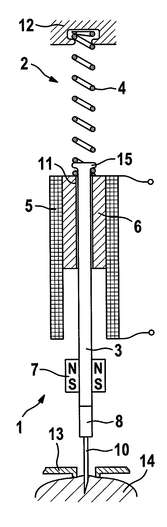
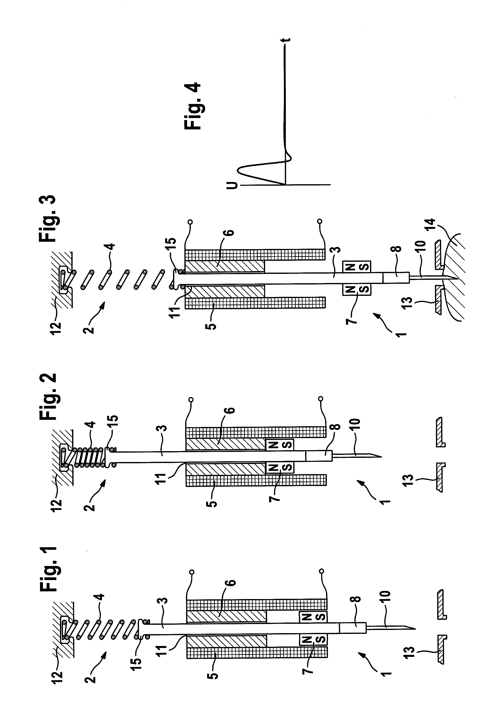
[0045]The lancet devices 1 illustrated in FIGS. 1 through 3 and in FIG. 5 may be integrated in a handheld analysis device, for example, which has a measuring apparatus for assaying body fluid, which is obtained from a generated piercing wound. The lancet devices may also be installed in a separate device such as a puncture aid.

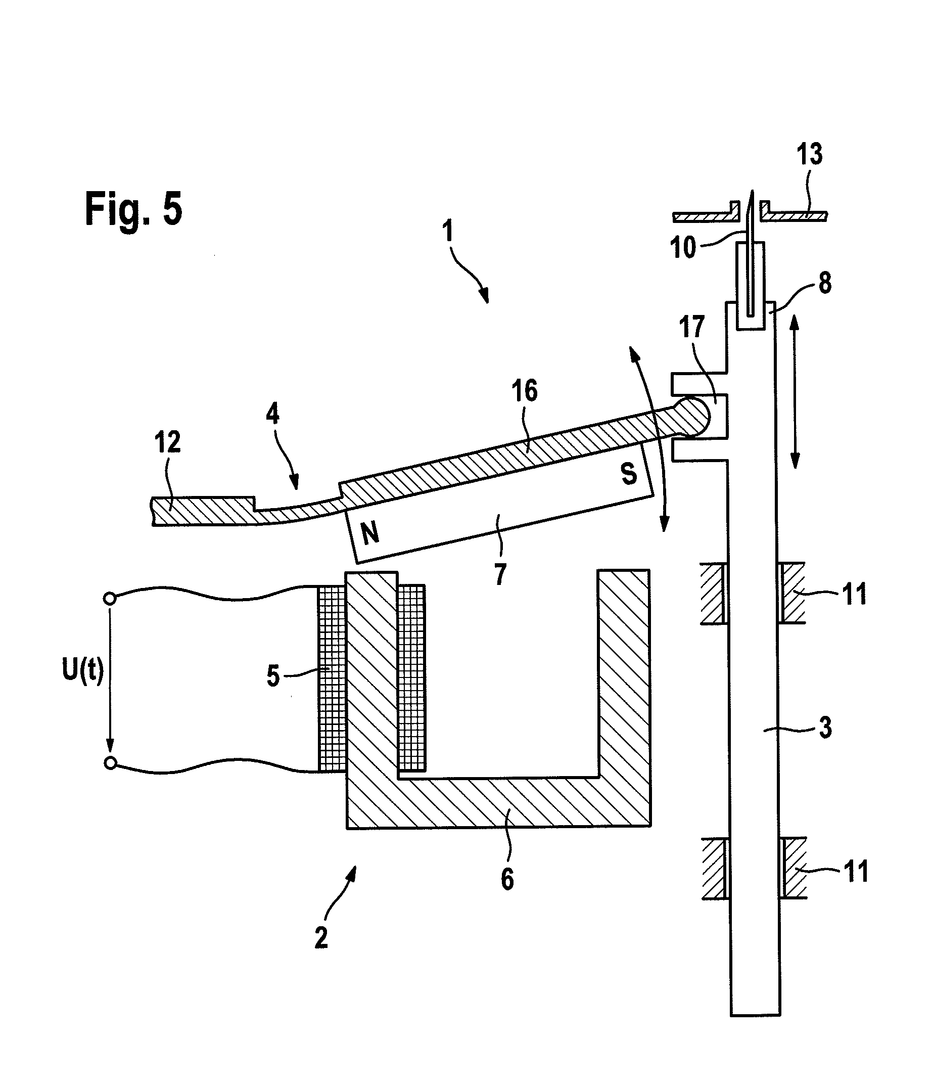
[0046]The central component of the lancet device 1 shown in FIGS. 1 through 3 is a lancet drive 2, which comprises a pushrod 3, which may also be referred to as a lancet guide, which is configured to hold a lancet 10 by means of lancet holder 8. A drive mechanism is provided in the form of a drive spring 4 ...


PUM


Abstract

The present invention relates to lancet device by which a lancet is displaceable along a piercing path to generate a piercing wound in a skin surface, in particular to obtain body fluid for diagnostic purposes. To achieve performance of a piercing movement which is low in noise and shock, the lancet drive may include a control unit for regulating the piercing depth of the lancet and the lancet may be implemented to oscillate freely out in the piercing direction without delimitation by a mechanical piercing depth stop.

Description

RELATED APPLICATIONS[0001]This application claims priority to EP 07 005 231.1, filed Mar. 14, 2007, which is hereby incorporated herein by reference.BACKGROUND[0002]The present invention relates to a lancet device by which a lancet can be displaced along a piercing path to generate a piercing wound in a skin surface, in particular to obtain body fluid for diagnostic purposes, comprising a lancet drive, which has a drive for generating a drive force for a piercing movement of the lancet along the piercing path in the direction toward the skin surface, a retention means for generating a magnetic retention force for retaining the lancet in a tensioned position, and a trigger by which the retention force is reducible enough that the lancet is accelerated in the direction toward the skin surface under the effect of the drive force generated by the drive means.[0003]Furthermore, the present invention relates to a method for operating a lancet device, by which a lancet is displaced along a...

Claims


Application Information

Patent Timeline
18 Sep 2008
Publication
US20080228212A1
IPC
A61B5/151
CPC
A61B5/1411; A61B5/150022; A61B5/150167; A61B5/150175; A61B5/150412; A61B5/150503; A61B5/15117; A61B5/15123
Inventors
LIST, HANS