
Moist organic product drying system having a rotary waste heat evaporator

a technology of organic products and waste heat evaporators, which is applied in drying machines, lighting and heating apparatus, furniture, etc., can solve the problems of inability to adequately control both the temperature of thermal oxidizers and oxygen concentrations, and the reduction of voc and co content to the atmosphere, so as to achieve the effect of reducing voc and co conten

Active Publication Date: 2008-09-25
AEROGLIDE
View PDF5 Cites 17 Cited by
  • Summary
  • Abstract
  • Description
  • Claims
  • Application Information

AI Technical Summary

Benefits of technology

This patent describes an improved system that uses two stages of heat exchange to recover energy from exhaust gases released by industrial equipment such as power generators or chemical reactors. By redirecting some of this excess heat into other processes, the system can improve efficiency and reduce emissions.

Problems solved by technology

This patent discusses how dryers are commonly used to remove excess moisture from various organic materials like grain or alcohol plant waste. However, with the increasing production of these materials, there is an increase in emissions (VOCs and CO) released during this process. To address this issue, the patent proposes a new design for dryers that can effectively decrease these emissions through the use of a thermal oxidizer. Previous designs had limitations on controlling the temperature and oxygen concentration of the oxidizer, resulting in less effective removal of emissions. Therefore, the technical problem addressed by this patent is finding ways to improve the efficiency of reducing emissions from dried organic material using a thermal oxidizer.

Method used


Image

  • Moist organic product drying system having a rotary waste heat evaporator
  • Moist organic product drying system having a rotary waste heat evaporator
  • Moist organic product drying system having a rotary waste heat evaporator

Examples


Embodiment Construction

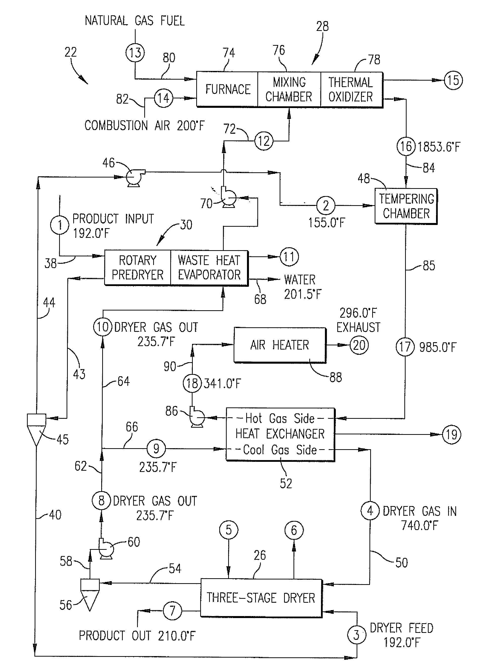
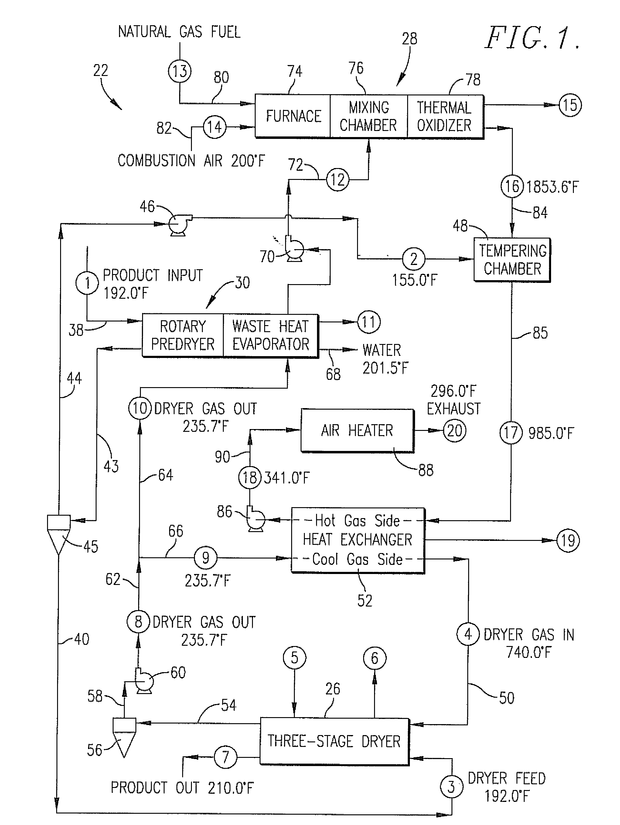
[0028]FIG. 1 illustrates an exemplary process 22 according to the present invention for reducing the VOC and CO content of dryer offgas that is discharged into the atmosphere from a moist organic product drying process. The process employs a predryer / waste heat recovery unit 24 (shown schematically in FIG. 6) in order to remove moisture from the moist product. Unit 24 also removes moisture from the dryer offgas so that higher thermal oxidizer temperatures may be achieved while maintaining a sufficient level of oxygen in the output from the thermal oxidizer. As explained hereunder, unit 24 is integrated with a primary product dryer 26 and thermal oxidizing apparatus 28 in order to achieve thermal oxidation of pollutants present in the dryer offgas prior to discharge to the atmosphere.

[0029]Moist product to be dried is initially fed to a rotary waste heat evaporator 30, also referred to herein as a predryer, by way of a product conveyor 32. Typically, the moist product supplied to pro...


PUM


Abstract

A method and apparatus are provided for reducing the VOC and CO content of dryer offgas that is discharged into the atmosphere from a moist organic product drying process using thermal oxidizing apparatus that includes a furnace, mixing chamber, thermal oxidizer, tempering chamber, and an indirect gas-to-gas heat exchanger. The dryer offgas is separated into two portions, with a larger portion being preheated by indirect heat exchange with the hot gaseous output from the thermal oxidizer. The non-preheated portion is directed to a rotary waste heat evaporator in which moisture is removed therefrom. The preheated portion is recycled to the hot gas inlet of the dryer and serves the function of dryer heat transfer media. By removing moisture from the non-preheated portion of the offgas that is directed to the thermal oxidizing apparatus, simultaneous achievement of thermal oxidizer temperatures of 1600° F. or greater, and an adequate oxygen concentration of 5% by volume is achieved for optimized thermal oxidation of carbon monoxide and volatile organic compounds.

Description


Claims


Application Information

Patent Timeline
Owner AEROGLIDE
Learn More