Process for Preparing Front Filter for Plasma Display Panel

a plasma display panel and front filter technology, applied in the manufacture of tubes/lamp screens, gas discharge vessels/containers, chemical instruments and processes, etc., can solve the problems of low color purity of orange light emitted, high photopic reflection on the surface, and harmful electromagnetic interference, etc., to achieve no exterior defects and high transparency

Inactive Publication Date: 2008-09-25
SKC HAAS DISPLAY FILMS CO LTD
View PDF1 Cites 17 Cited by
  • Summary
  • Abstract
  • Description
  • Claims
  • Application Information

AI Technical Summary

Benefits of technology

[0006]Accordingly, it is an object of the present invention to provide an improved method for preparing a PDP front filter hav

Problems solved by technology

PDP is known to be more suitable for a high definition television (HDTV) having an enlarged, flat frame than a cathode ray tube (CRT) or a liquid crystal display (LCD), but has the problems of: releasing harmful electromagnetic interference(EM)/infrared(IR) emissions; high photopic reflection on the surface thereof; and lower color purity than CRT caused by ora

Method used


Image

  • Process for Preparing Front Filter for Plasma Display Panel
  • Process for Preparing Front Filter for Plasma Display Panel
  • Process for Preparing Front Filter for Plasma Display Panel

Examples


example 1

Step 1) Preparation of a Coating Solution for NIR Film

[0029]300 g of poly(methyl methacrylate) (PMMA) was dissolved in 1000 ml of methylethylketone (MEK) with heating. 1 g of octaphenyl tetraazaporphyrin (disclosed in Korean Patent Laid-open Publication No. 2001-26838) and 15 g of IRG022® (Nippon Chemical pharmaceutical Co.) were added thereto. To the resulting solution, 120 mg of Acridine Orange® (Aldrich Chemical Co.) dissolved in 50 ml of isopropyl alcohol (IPA) was slowly added to obtain a coating solution for NIR film comprising an NIR cutting pigment and a selective optical absorbent pigment.

Step 2) Preparation of NIR Cutting / Selective Optical Absorbent Film

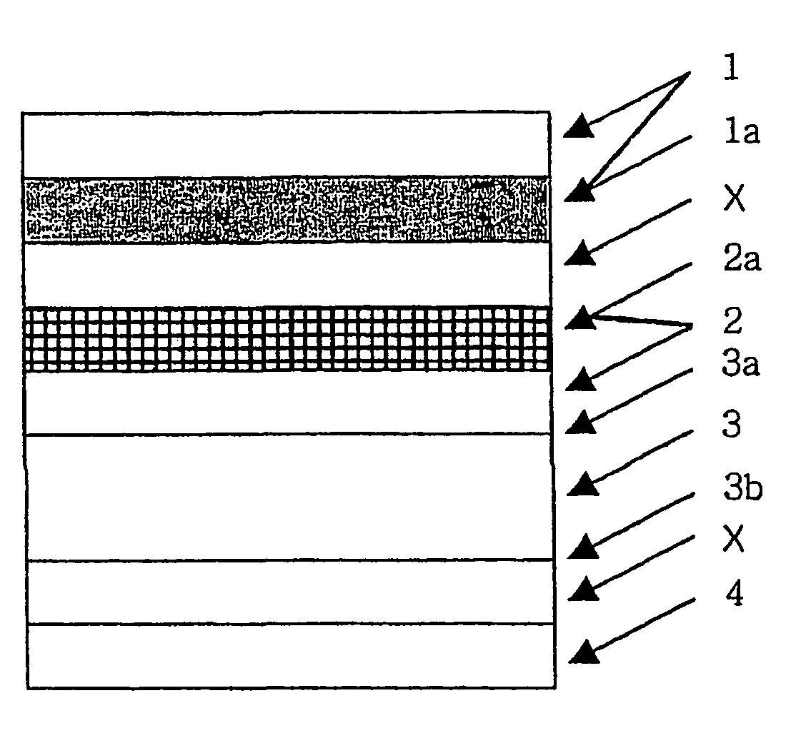
[0030]On one surface of a high transparent polyethylene terephthalate (PET) film of 125 μm thickness, the solution obtained in Step 1 was coated by a comma coating method and dried at 100° C. As a result, an NIR cutting / selective optical absorbent layer (1a) having a thickness of 10 μm was formed to obtain a NIR cutting / sel...

example 2

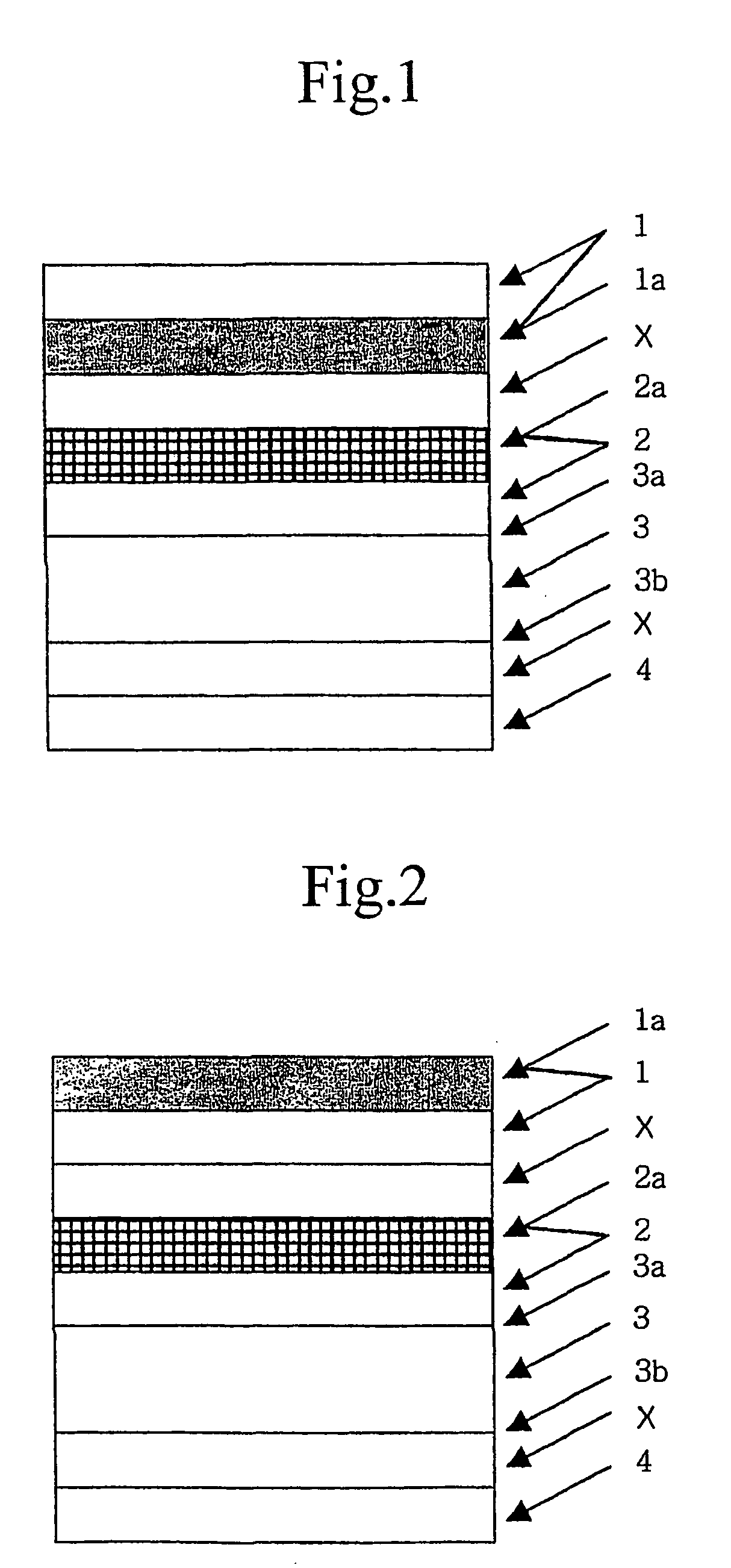
[0034]The procedure of Example 1 was repeated except that the adhesive layer (X) was formed on the base film layer of the NIR cutting / selective optical absorbent film, in Step 3; and in Step 4, the NIR cutting / selective optical absorbent film (1) was laminated on the conductive mesh film such that the base film layer of the NIR cutting / selective optical absorbent film came in contact with the copper mesh layer (2a) of the conductive mesh film, to obtain a PDD filter having the laminate structure shown in FIG. 2.

example 3

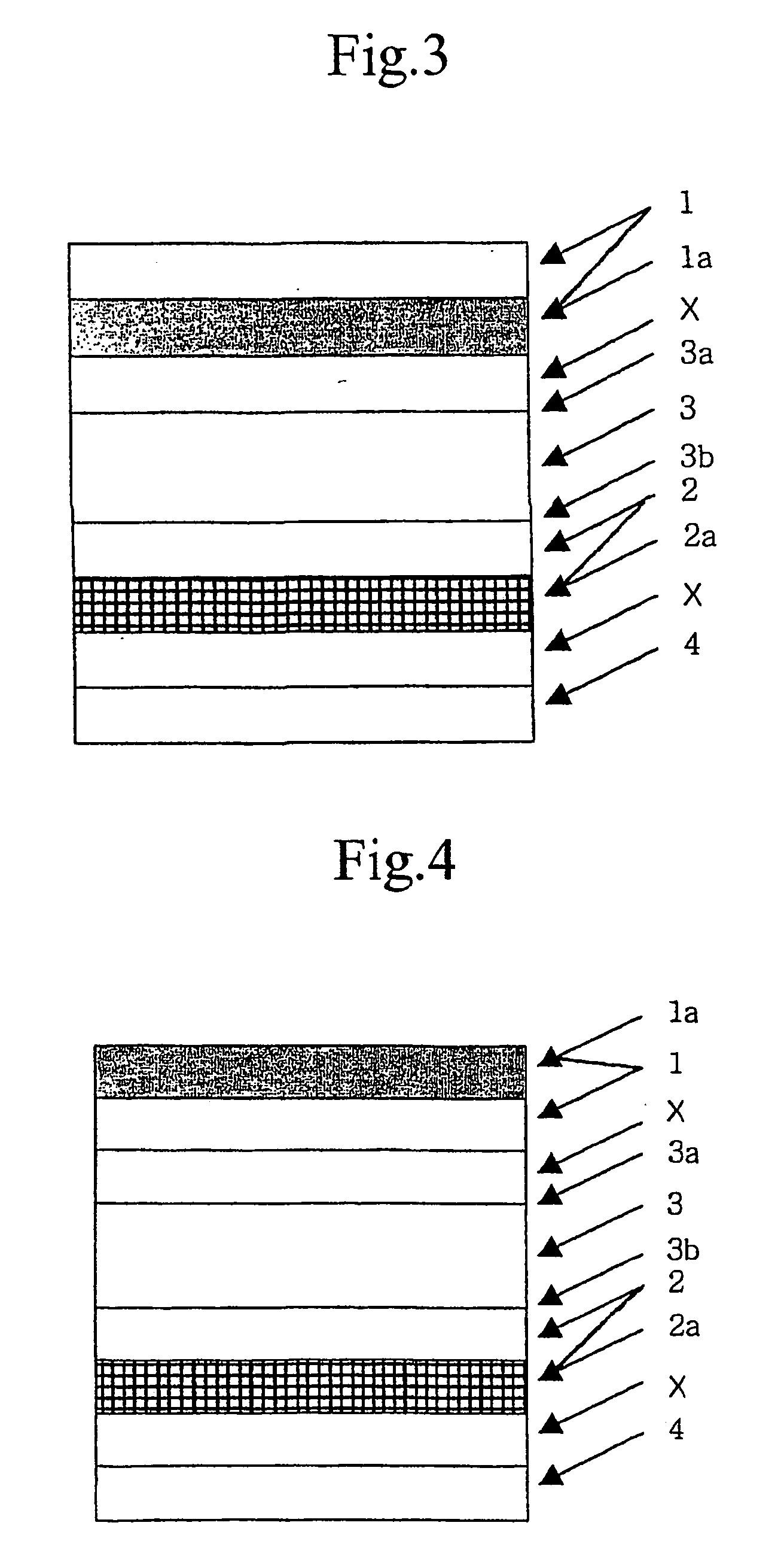
[0035]The procedure of Example 1 was repeated except that the conductive mesh film (2) was laminated on the front side (3b) of the transparent glass substrate (3); the AR film (4) was further laminated on the metallic mesh layer (2a); and the NIR cutting / selective optical absorbent film (1) was laminated on the back side (3a) of the transparent glass substrate (3) such that the NIR cutting / selective optical absorbent layer (1a) came in contact with the transparent glass substrate (3), in Step 4, to obtain a PDD filter having the laminate structure shown in FIG. 3.


PUM

PropertyMeasurementUnit
Temperatureaaaaaaaaaa
Thicknessaaaaaaaaaa
Pressureaaaaaaaaaa

Abstract

A plasma display panel (PDP) filter having a high transparency and no exterior defect can be simply prepared by a method comprising the steps of a) laminating a conductive mesh film having a metallic mesh layer formed on a base film, on a transparent glass substrate such that the base film of the conductive mesh film comes in contact with the transparent glass substrate, to obtain laminate A; b) forming a transparent adhesive layer on one surface of an optic film, to obtain laminate B; c) laminating laminate A and laminate B such that the adhesive layer of laminate B comes in contact with the metallic mesh layer of laminate A, to obtain laminate C; and d) heating and pressing laminate C in an autoclave to allow the adhesive layer of laminate B attach to the metallic mesh layer of laminate A.

Description

FIELD OF THE INVENTION[0001]The present invention relates to a simple and economic method for preparing a front filter for a plasma display panel (PDP) having superior performance characteristics.BACKGROUND OF THE INVENTION[0002]PDP is known to be more suitable for a high definition television (HDTV) having an enlarged, flat frame than a cathode ray tube (CRT) or a liquid crystal display (LCD), but has the problems of: releasing harmful electromagnetic interference(EM) / infrared(IR) emissions; high photopic reflection on the surface thereof; and lower color purity than CRT caused by orange light emitted from injected Ne gas. Accordingly, a filter has been applied in front of PDP to solve the above problems.[0003]Such a PDP front filter is designed to comprise a conductive mesh film that is bound to metal mesh pattern at one side of a base film, for shielding against EMI emission. However, the poor light transmittance of such mesh pattern deteriorates filter transparency.[0004]To solv...

Claims


Application Information

Patent Timeline
IPC IPC(8): B32B37/02H01J9/24H01J11/10H01J11/44H01J17/49
CPCG02B5/20H01J9/205H05K9/0096H01J11/44H01J2211/446H01J11/10E03C1/22E03C1/182
Inventor CHO, KYOO CHOONGPARK, CHAN HONGPARK, PYUNG GUK
Owner SKC HAAS DISPLAY FILMS CO LTD
Why Eureka
Try Eureka