Eureka AIR delivers breakthrough ideas for toughest innovation challenges, trusted by R&D personnel around the world.

Instantaneous measurement of drillstring orientation

Active Publication Date: 2008-09-25
BAKER HUGHES INC
View PDF9 Cites 30 Cited by
  • Summary
  • Abstract
  • Description
  • Claims
  • Application Information

AI Technical Summary

Benefits of technology

[0008]In one aspect, an orientation measurement system is deployed in a wellbore drilling system having at least one rotating section and one or more non-rotating sections. One or more reservoir imaging and characterization tools, directional tools, and/or other known bottomhole assembly (BHA) tools are positioned in the rotating section. The non-rotating section can include a non-rotating sleeve associated with a stabilizer or a steering unit. The orientation measurement system includes a processor, a rotary position sensor and an orientation sensor. The processor receives signals from the rotary position sensor, which measures an angular position of the rotating section relative to the non-rotating section. The processor also receives signals from the orientation sensor, which determines the orientation of the non-rotating section relative t

Problems solved by technology

Conventionally, the methodology for determining a toolface of an imaging sensor involves the use of magnetic sensing devices because the shocks, vibrations, and centrifugal forces associated with a rotating system can unduly interfere with the operation of devices such as accelerometers that could provide a direct measurement of highside.
The problems encountered with such conventional devices and methods include inaccurate or outdated conversions between magnetic toolface and highside, inaccuracy due to magnetic junk or hotspots, eddy currents induced in a rotating conductive collar, and errors caused by electric currents flowing in proximity to the sensor.
In addition, while it is desirable to continuously measure the azimuth of the borehole while drilling, the value of such measurements has been limited due to the difficulty of accurately measuring transverse acceleration components of a rotating system.

Method used


Image

  • Instantaneous measurement of drillstring orientation
  • Instantaneous measurement of drillstring orientation
  • Instantaneous measurement of drillstring orientation

Examples


Embodiment Construction

[0016]The present invention relates to devices and methods providing orientation information for drilling system adapted to drill a wellbore in a subterranean formation. The present invention is susceptible to embodiments of different forms. There are shown in the drawings, and herein will be described in detail, specific embodiments of the present invention with the understanding that the present disclosure is to be considered an exemplification of the principles of the invention, and is not intended to limit the invention to that illustrated and described herein.

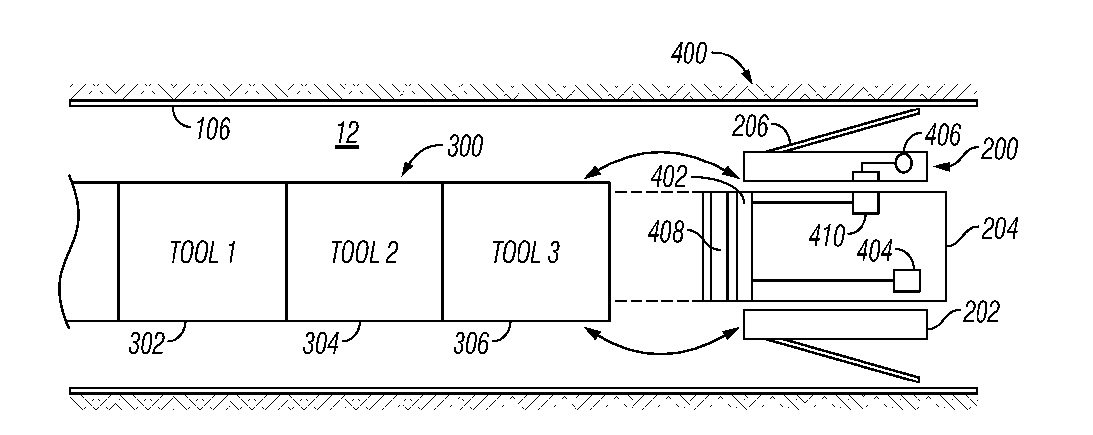
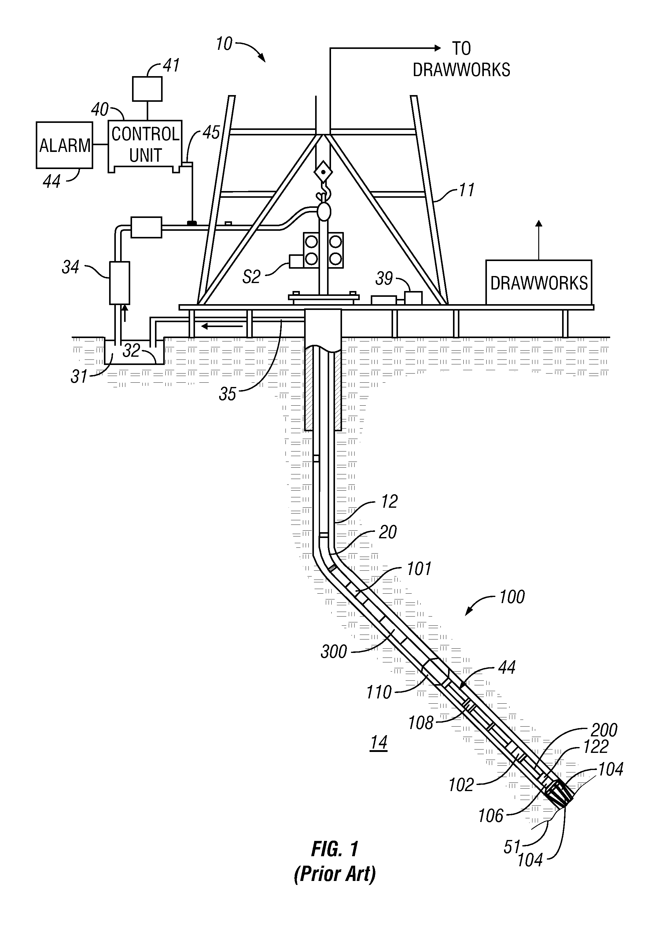
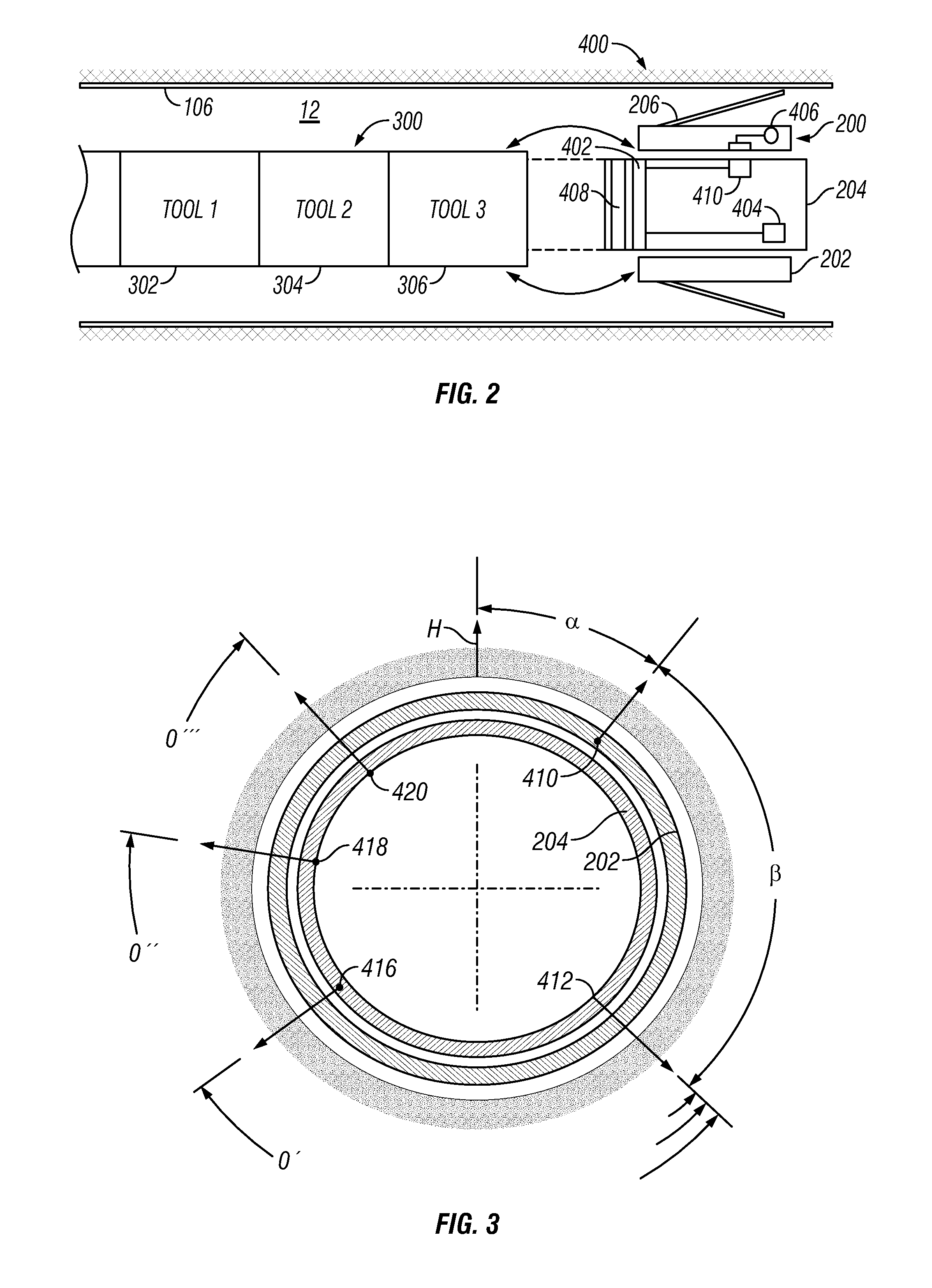
[0017]Referring initially to FIG. 1 there is shown a schematic diagram of a drilling system 10 having a bottom hole assembly (BHA) or drilling assembly 100 conveyed via a drill string 20 into a borehole 12 formed in a formation 14. The BHA 100 includes a drilling motor 102 for rotating a drill bit 104, a steering assembly 106 for steering the drill bit 104 in a selected direction, one or more BHA processors 108, one or mor...


PUM


Abstract

An orientation measurement system is deployed in a wellbore drilling system having one or more reservoir imaging and characterization tools, directional tools, and / or other known BHA tools in a rotating section. The orientation measurement system includes a processor receiving signals from a rotary position sensor measuring an angular position of the rotating section relative to the non-rotating section and receiving signals from an orientation sensor determining the orientation of the non-rotating section relative to a reference frame such as highside. The processor uses the first and second signals to determine a tool face of the rotating member relative to the highside and periodically and / or continuously transmits the determined tool face along the BHA via a suitable communication link. The determined tool face is used by the BHA tools to synchronize measurements with highside and / or to determine azimuth.

Description

CROSS REFERENCE TO RELATED APPLICATIONS[0001]This application takes priority from U.S. Provisional Application Ser. No. 60 / 844,185 filed on Sep. 13, 2006.BACKGROUND OF THE INVENTION[0002]1. Field of the Invention[0003]This invention relates generally to drilling assemblies that utilize an orientation sensing system.[0004]2. Description of the Related Art[0005]Valuable hydrocarbon deposits, such as those containing oil and gas, are often found in subterranean formations located thousands of feet below the surface of the Earth. To recover these hydrocarbon deposits, boreholes or wellbores are drilled by rotating a drill bit attached to a drilling assembly (also referred to herein as a “bottom hole assembly” or “BHA”). Such a drilling assembly is attached to the downhole end of a tubing or drill string made up of jointed rigid pipe or a flexible tubing coiled on a reel (“coiled tubing”). For directional drilling, the drilling assembly can use a steering unit to direct the drill bit alo...

Claims


Application Information

Patent Timeline
IPC IPC(8): E21B47/09
CPCE21B47/024
Inventor BROOKS, ANDREW G.
Owner BAKER HUGHES INC
Why Eureka
Eureka Blog
Learn More