Handling Device For Elements of Tapping Runners

a technology of a handling device and a runner, which is applied in the direction of lighting and heating apparatus, blast furnace components, blast furnaces, etc., can solve the problems of inability to facilitate handling operations, relatively limited flexibility in and the type of device according to jp 10-317026 is also limited in its ability of positioning and orienting the runner cover. , to achieve the effect of high flexibility of positioning

Inactive Publication Date: 2008-09-25
TMT TAPPING MEASURING TECH
View PDF4 Cites 8 Cited by
  • Summary
  • Abstract
  • Description
  • Claims
  • Application Information

AI Technical Summary

Benefits of technology

[0010]The invention provides a handling device for elements of tapping runners, in particular for runner covers, which is capable of handling ...

Problems solved by technology

Such handling operations are not facilitated by the usual dimensions and weight of the runner cover.
The aforementioned known devices have the common drawback that they are relatively limited in their flexibility for positioning and orienting a runner cover.
Nevertheless, the type of device according to JP 10-317026 is also limited in its capabilities of positioning and orien...

Method used


Image

  • Handling Device For Elements of Tapping Runners
  • Handling Device For Elements of Tapping Runners
  • Handling Device For Elements of Tapping Runners

Examples


first embodiment

[0040]FIG. 5 shows a plan view of different postures of the handling device 10 in a blast furnace installation. In FIG. 5, a blast furnace 75 and a first and a second runner 76, 78, which are proximate and extend radially from the blast furnace 75, are very schematically indicated. The blast furnace 75 may comprise e.g. two more runners and, associated thereto, an additional handling device on the opposite side (not shown). The first runner cover 70 is shown in an operating position 81 and in a garage position 82. A second runner cover 70′ is also shown in an operating position 83 and in a garage position 84. For each position 81, 82, 83, 84, a corresponding posture of the handling device 10 is shown in FIG. 5. Of course, the handling device 10 is capable of serving at various other positions within its working range, depending on the actual architecture of a blast furnace installation. Hence, the single handling device 10 is capable of bringing both the first runner cover 70 and t...

third embodiment

[0043]FIG. 7 shows a handling device 210 according to the invention. Only the differences with respect to the previous embodiments are detailed below. Similar or identical parts are referenced in FIG. 7 with reference numerals having identical units and tens digits but a hundreds digit increased by one. Whereas the previously described embodiments each possess one forward / backward (translational) degree of freedom (DOF) and three rotational DOF, the handling device 210 is designed with three rotational DOF about axes A, B, C only. Hence, the handling device 210 is devoid of any translational DOF. The fork type grab 226 of the handling device 210 is provided with a first and a second lifting pin 227 and 229, fixed essentially perpendicular to the prongs 272. Instead of handling bars, the runner covers 270, 270′ adapted for the handling device 210 comprise eyelet flanges 273 having eyelets matching the lifting pins 227 and 229 of the handling device 210. Due to this arrangement, the h...


PUM

PropertyMeasurementUnit
Angleaaaaaaaaaa
Angleaaaaaaaaaa
Distanceaaaaaaaaaa

Abstract

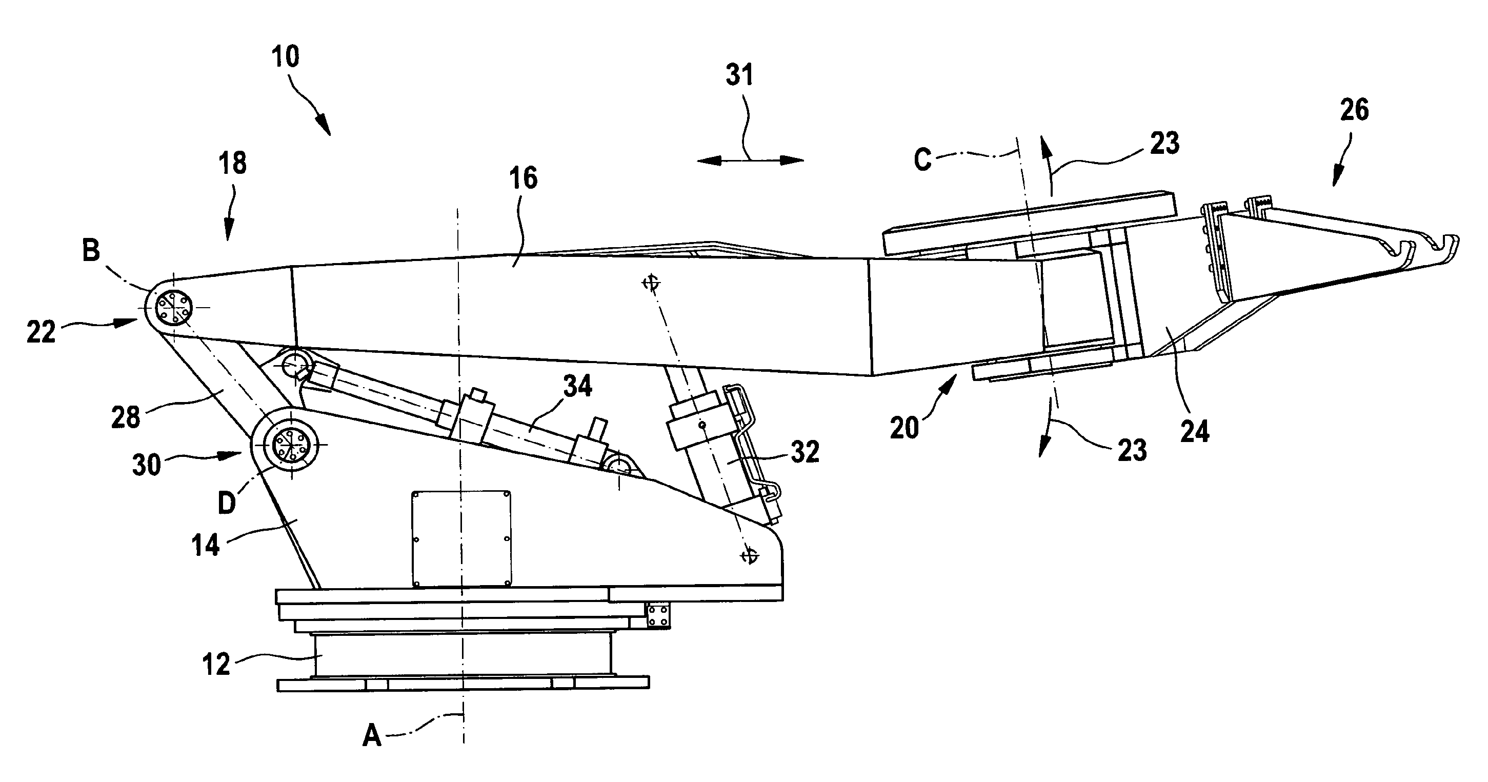
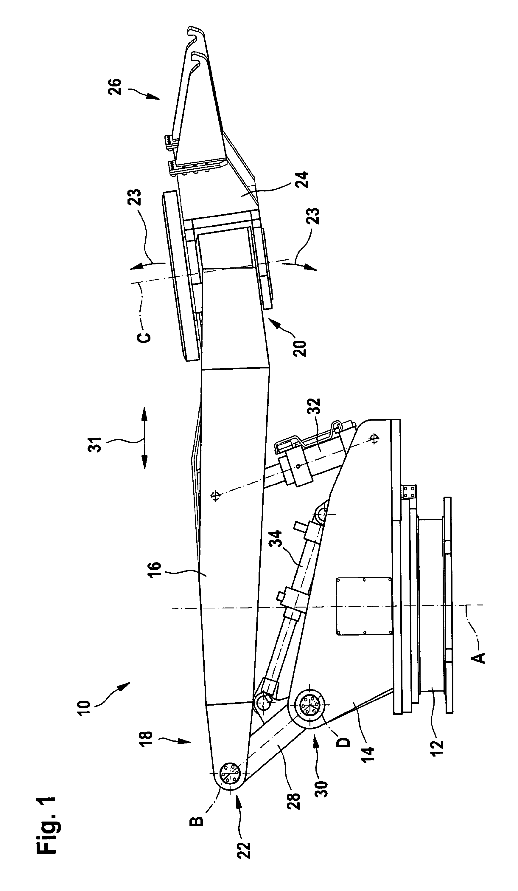
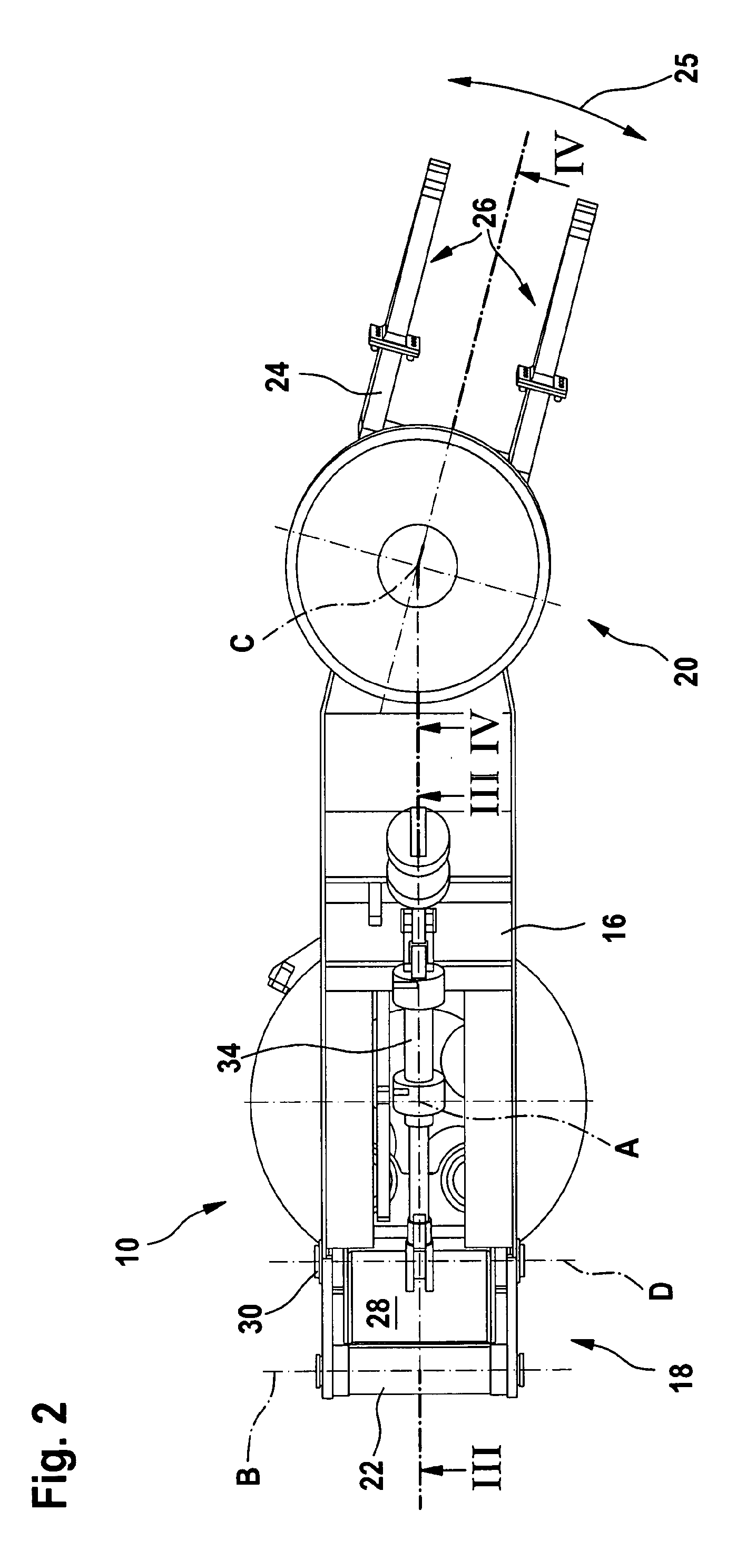
A handling device for elements of tapping runners on a shaft furnace, in particular for runner covers, the device including a support base arranged on the cast house floor of a blast furnace, laterally of the tapping runner and a frame (14) which is supported by the support base and connected thereto by means of a bearing defining a first axis of rotation, which is essentially vertical and about which the frame can rotate relative to the support base. The device further includes a lifting arm having a first end portion and a second end portion, the first end portion being connected to the frame by means of at least a first rotational joint defining a second axis of rotation, which is essentially horizontal, about which the lifting arm can pivot in order to lower or lift its second end portion. A handling member is connected to the second end portion of the lifting arm by means of a second rotational joint defining a third axis of rotation, which lies in a plane essentially perpendicular to the second axis of rotation, about which the handling member can pivot with respect to the lifting arm. Furthermore, the handling device includes a fork-type grab connected to the handling member and arranged so as to allow picking up; transferring and putting down such elements.

Description

TECHNICAL FIELD OF THE INVENTION[0001]The present invention relates to a handling device for elements of tapping runners on a shaft furnace, in particular for runner covers of blast furnace main runners.BRIEF DISCUSSION OF RELATED ART[0002]In order to reduce detrimental emissions and heat radiation in the cast house of a blast furnace, it is known to cover a tapping runner (also called launder or trough) by at least one mobile cover elements. Such runner covers consist of an elongated metallic case fitted with an inward refractory protection. Their dimensions can amount to several meters in length and some meters in width. Their weight may significantly exceed 10'000 kg.[0003]For tapping and plugging the taphole however, it is necessary to remove the upstream runner cover, i.e. the runner cover which is located immediately downstream the taphole. The upstream runner cover is normally put into a parking position and put back in front of the taphole afterwards. Such handling operation...

Claims


Application Information

Patent Timeline
IPC IPC(8): F27D3/14C21B7/00F27D99/00
CPCC21B7/14F27D3/145F27D3/14C21B7/00
Inventor GORZA, ROBERTKREUZ, HANS-OTTOTAUGERBECK, RALF
Owner TMT TAPPING MEASURING TECH
Why Eureka
Try Eureka