Turbo Generator With Exciter Having Pressure Recovery

Active Publication Date: 2008-09-25
GENERAL ELECTRIC TECH GMBH
View PDF8 Cites 5 Cited by
  • Summary
  • Abstract
  • Description
  • Claims
  • Application Information

AI Technical Summary

Benefits of technology

[0009]Accordingly, the technical problem to be solved by the present invention is to avoid the described draw backs of

Problems solved by technology

This conflicts with limitations in space available at the respective site of the power plant.
The tan

Method used


Image

  • Turbo Generator With Exciter Having Pressure Recovery
  • Turbo Generator With Exciter Having Pressure Recovery
  • Turbo Generator With Exciter Having Pressure Recovery

Examples


Embodiment Construction

[0025]Referring now to the drawings, wherein like reference numerals designate identical or corresponding parts throughout the several views, preferred exemplary embodiments of the invention are reproduced in FIGS. 1 through 5. The drawings are merely schematic sketches and serve explicatory reasons only.

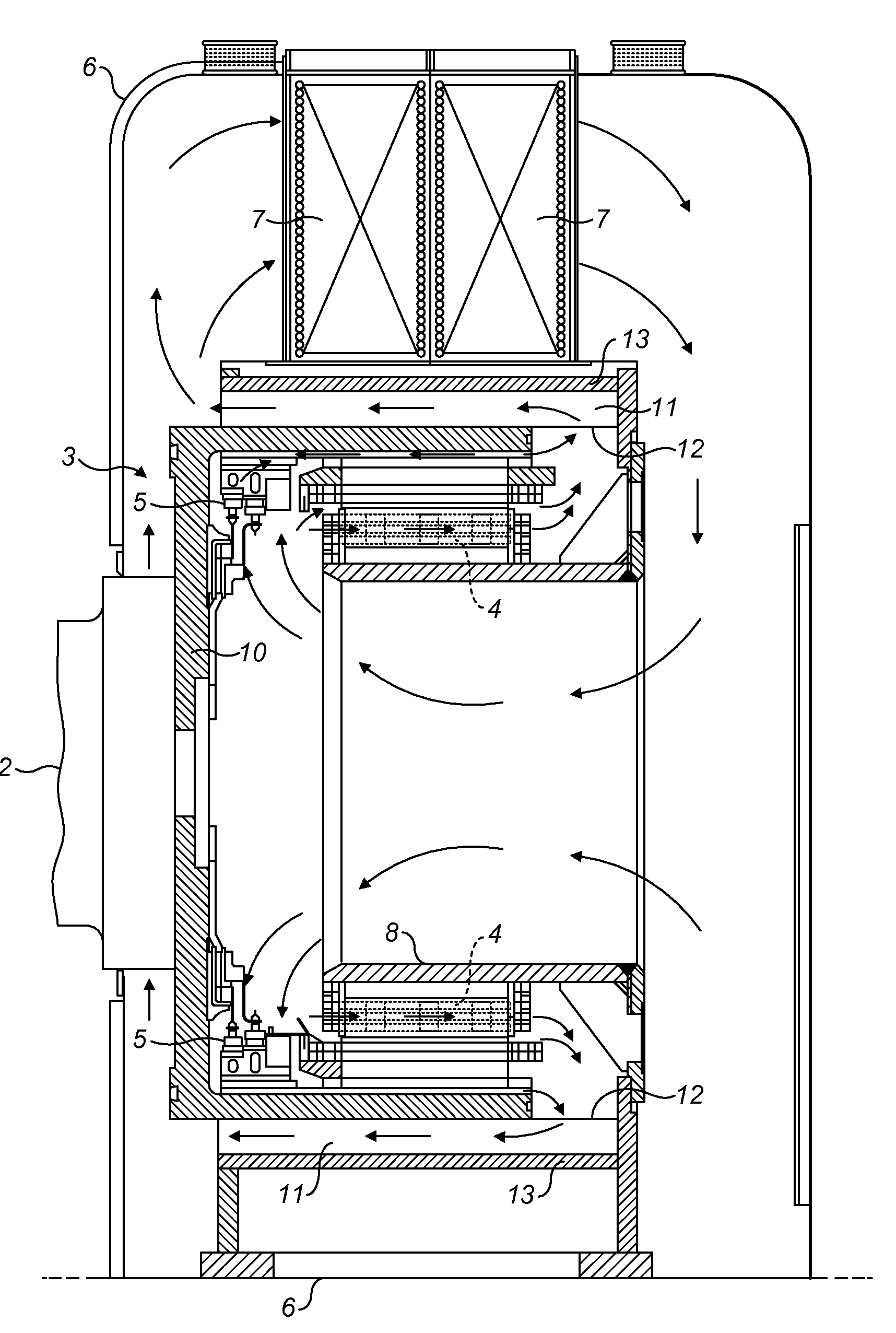
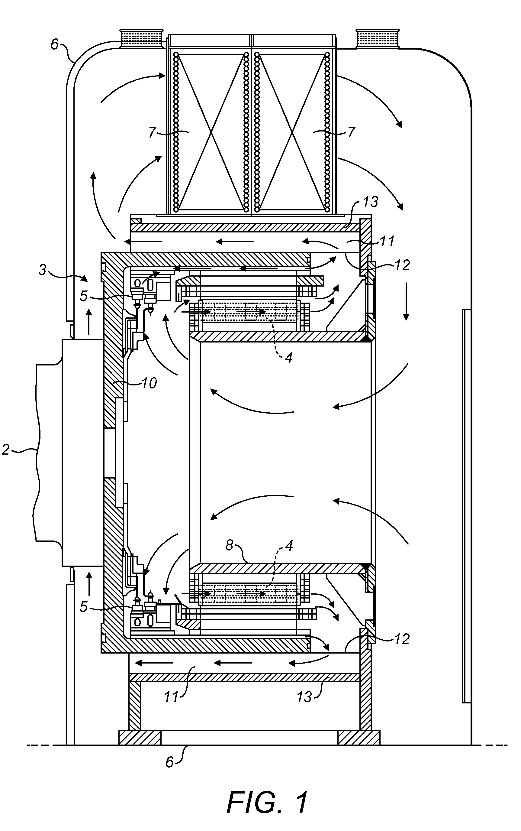
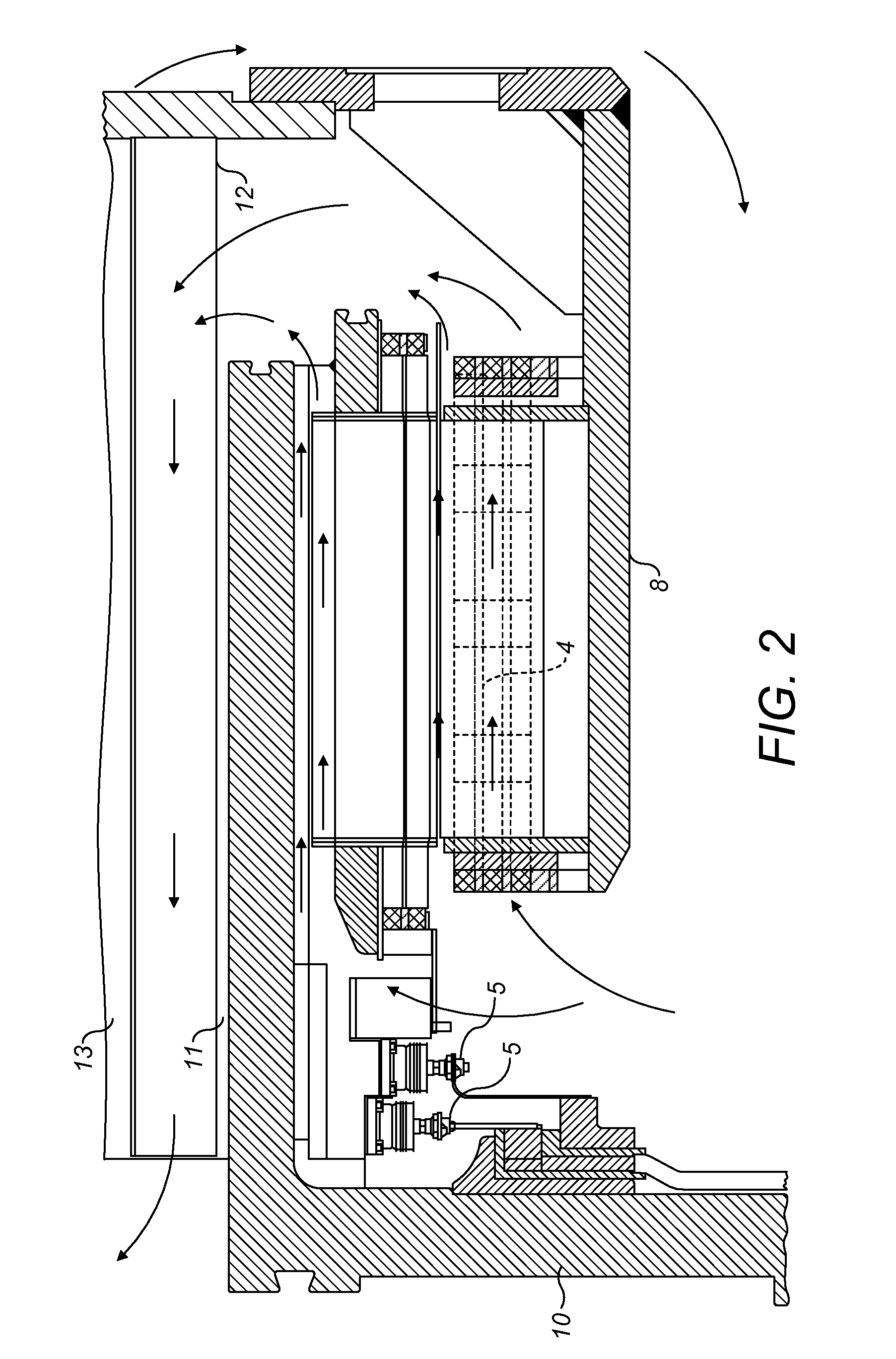
[0026]FIG. 1 shows a schematic sectional view of a bell type exciter 3 having an axial duct 11 with a guide 12 according to a preferred embodiment of the present invention. FIG. 2 shows a detail of FIG. 1.

[0027]The turbo generator has its rotor 2 connected to one end to the bell type exciter 3. The exciter 3 has on its inner circumference multi-phase windings 4 arranged on top of the lamination 21 and rotating around a static portion 8. There is a small gap 22 between the windings 4 and the static portion 8 which allows a cooling fluid flow going therethrough. The exciter current is passed through diodes 5 to convert the alternating current into direct current and then fed into the ...


PUM


Abstract

A turbo generator (1), including a stator and a rotor (2), has a rotating bell type exciter (3) connected to one end of the rotor (2) and the exciter (3) being equipped with at least one cooler (7). An axial duct (11) with a guide (12) is provided between a cylindrical housing (13) and the outer circumference of the bell type exciter (3). Thus, drawbacks of the prior art are mitigated and the efficiency of the bell type exciter is increased by recovering the dynamic energy of the cooling fluid flow.

Description

BACKGROUND[0001]1. Field of the Invention[0002]The present invention relates to a turbo generator having a stator and a rotor, a rotating bell type exciter connected to one end of the rotor, and being equipped with at least one cooler.[0003]2. Brief Description of the Related Art[0004]Large turbo generators for producing electric energy are designed as three-phase synchron machines having a stator and a rotor. One end of the rotor is connected to a turbo machine while the other end is connected to an exciter.[0005]European patent application EP 1 443 639 A1 (see also U.S. Pat. No. 6,844,639) by the same assignee discloses the electrical function of a rotating exciter for large currents. The rotor has at least two conducting rods essentially parallel to the rotor axis and connected at their first end to a collector ring and connected at their other ends to individual rings via diodes of opposite polarity so that the a.c. current induced in the rods as a result of a static field is co...

Claims


Application Information

Patent Timeline
IPC IPC(8): H02K9/00H02K9/26
CPCH02K5/20H02K19/38H02K9/12H02K5/207
Inventor VERRIER, MICHELPERROS, OLIVIERDIESTEL-FEDDERSEN, LENNART
Owner GENERAL ELECTRIC TECH GMBH
Why Eureka
Try Eureka