Data reader and positioning system

a data reader and positioning system technology, applied in wave based measurement systems, instruments, using reradiation, etc., can solve problems such as data read from radio ic tags

Active Publication Date: 2008-09-25
MYCLERK LLC
View PDF0 Cites 57 Cited by
  • Summary
  • Abstract
  • Description
  • Claims
  • Application Information

AI Technical Summary

Benefits of technology

[0008]The advantage of the present invention is to provide a data reader capable of changing an occurrence position of a dead spot (null point) as a point / area where it is difficult or impossible to read data due to the interference of radio waves for a read radiated from a data reader, and reading data regardless of a position of a radio IC tag.
[0009]As means for solving the above-mentioned problem, the present invention has the following features.
[0010]A data reader according to the present invention is proposed as a data reader for reading data in a separate position from a storage medium (for example, a radio IC tag) provided with a storage unit for storing data and a communicating antenna for transmitting data stored in the storage unit.
[0011]The data reader includes a plurality of antenna units for transmitting and receiving data with a storage medium; and a control unit (for example, a reader / writer or a reader / writer control device) connected to each antenna unit, wherein each antenna unit can change radiation characteristics (for example, an electric field pattern, a beam direction, a beam width, etc.) in accordance with the control unit.
[0012]According to the data reader, an occurrence of a dead spot due to a direct wave, reflected wave, etc. can be avoided by changing the radiation characteristic of antenna means, or a read disabled status due to a dead spot can be avoided by changing an occurrence position regardless of location of a storage medium, thereby performing a data read without failing in reading any data.
[0013]The above-mentioned data reader can further have the following feature. That is, the control unit changes the directivity of each antenna unit in conjunction with the directivities of other antenna units.

Problems solved by technology

As a result, a data read from the radio IC tag fails.
When a plurality of readers and a plurality of antennas for readers are provided, the radio waves for a read radiated from each antenna interfere with one another, and in a point where the above-mentioned interference occurs, a data read from a radio IC tag fails.

Method used


Image

  • Data reader and positioning system
  • Data reader and positioning system
  • Data reader and positioning system

Examples


first embodiment

A. First Embodiment

[0080][A.1. Basic Configuration]

[0081]The data reader according to the first embodiment is described below by referring to the attached drawings. First, an example of the basic configuration of the data reader according to an embodiment is explained below.

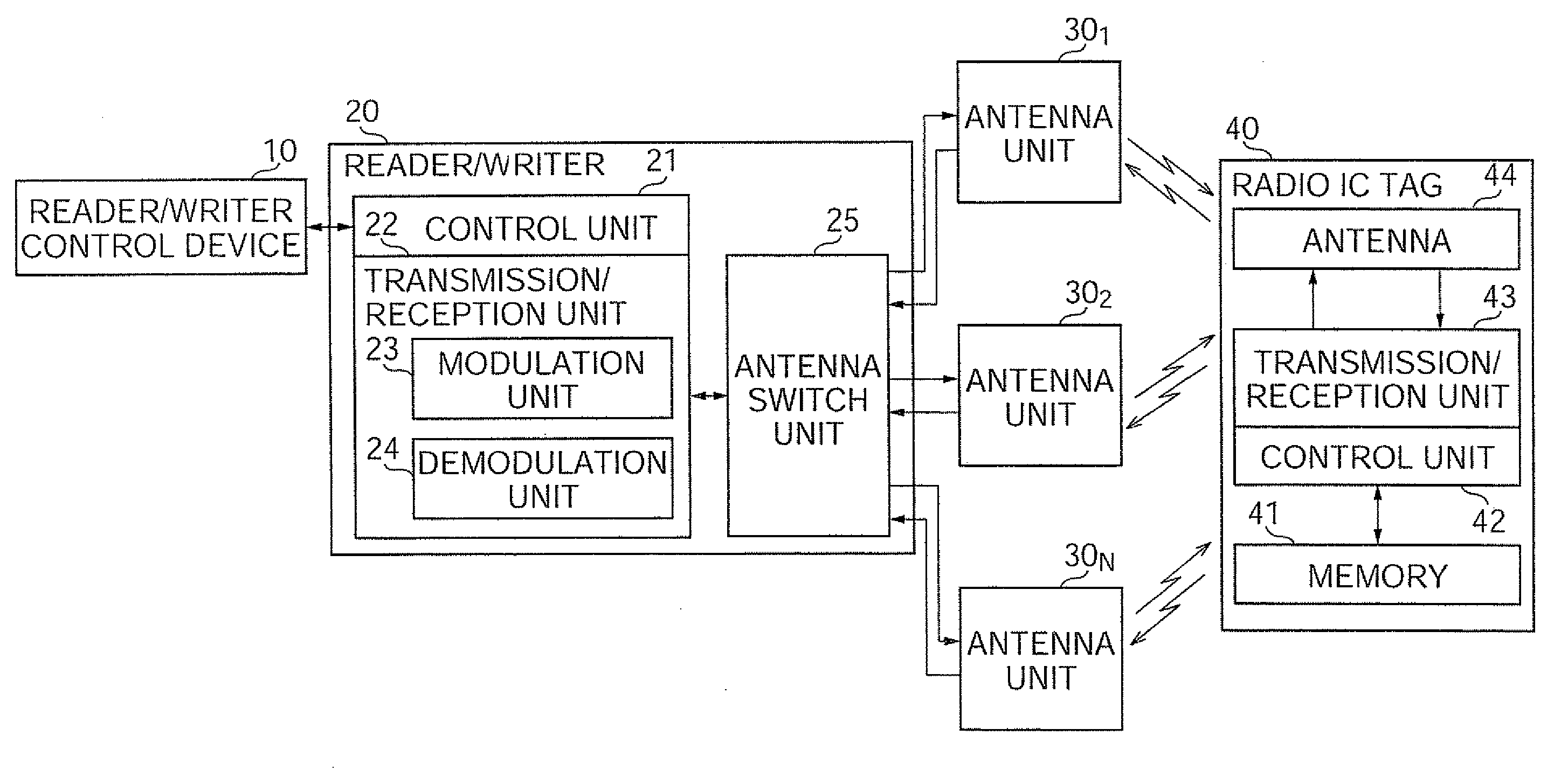
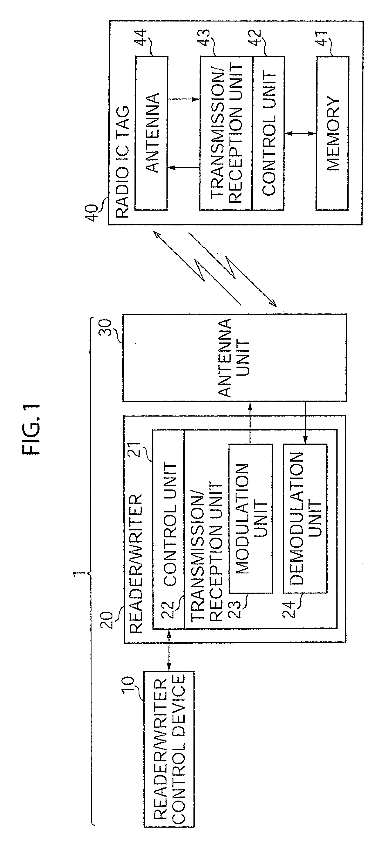
[0082]FIG. 1 is a block diagram showing the function of an example of the basic configuration of the data reader.

[0083]A data reader 1 is constituted by a reader / writer control device 10, a reader / writer 20 connected to the reader / writer control device 10, and an antenna unit 30 connected to the reader / writer 20.

[0084]The reader / writer control device 10 instructs the reader / writer 20 to perform a reading operation and transmit the data read from a radio IC tag 40 to the reader / writer 20, stores data received from the reader / writer 20, and performs predetermined information processing (for example, displaying an inventory list, etc.). The reader / writer control device 10 can be, for example, a computer, various con...

second embodiment

B. Second Embodiment

[0127]The second embodiment is explained below.

[0128]The second embodiment prevent failing in reading the radio IC tag 40 existing in the read target range by changing the position of the dead spot (null point) generated by the combination with a interference wave by the reader / writer 20 changing the phase of the radio waves for a read radiated from the antenna unit 30.

[0129]The configuration of the data reader according to the second embodiment is basically the same as the configuration of the data reader 1 according to the first embodiment, but it is different in that the modulation unit 23 of the reader / writer 20 has the function of adjusting the phase by shifting the phase of a carrier (carrier wave).

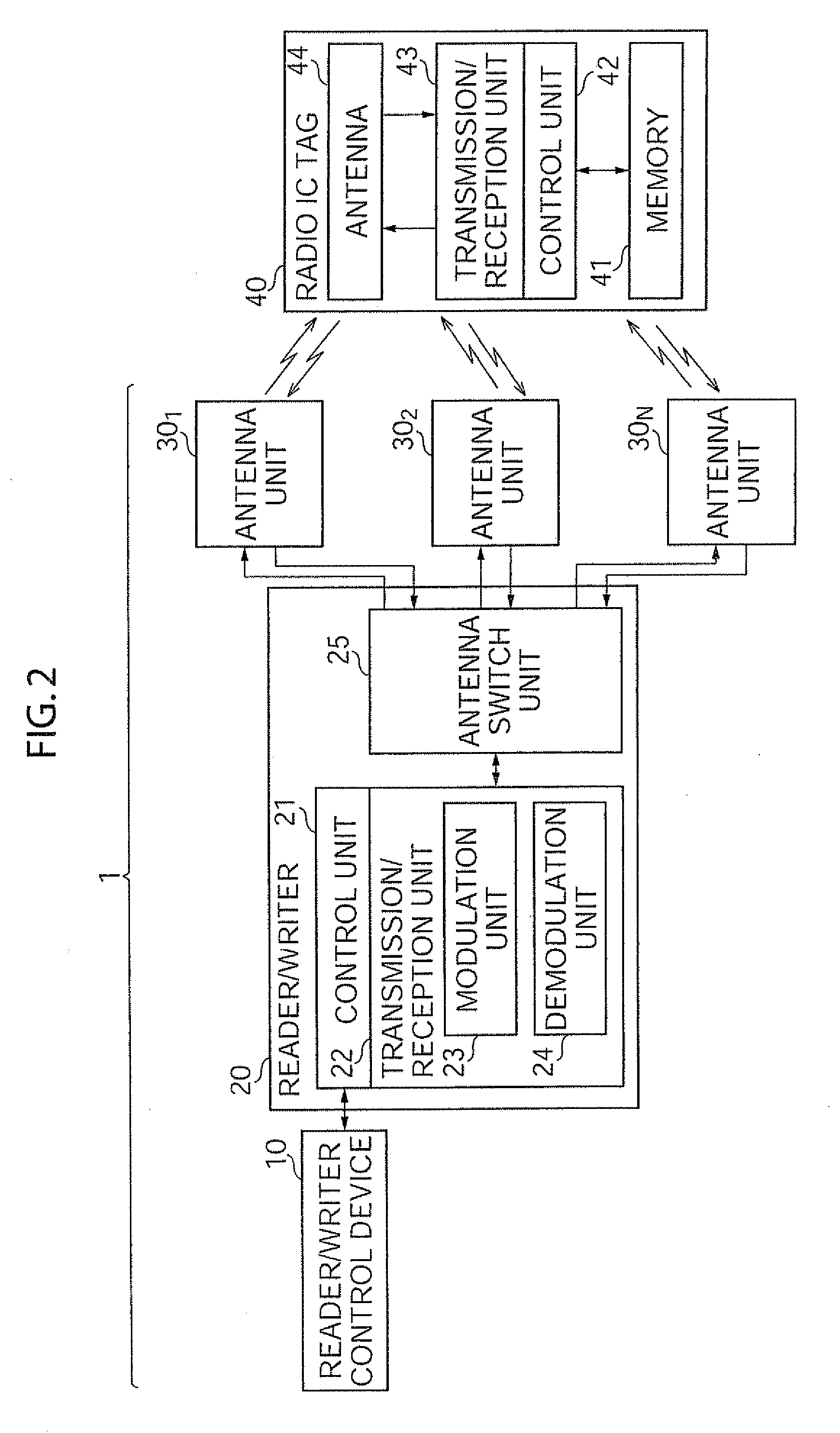
[0130]FIG. 12 is a block diagram showing the function of an example of the configuration of the reader / writer 20 according to the second embodiment.

[0131]The modulation unit 23 includes an oscillation circuit 1201 for generating a carrier signal, a phase adjustme...

third embodiment

C. Third Embodiment

[0141]The first and second embodiments can be applied to a positioning system for designating the position of the radio IC tag 40. The third aspect of the present invention is proposed as a system realized for designating a position with higher accuracy by reading the radio IC tag 40 depending on the dead spot in the positioning system for designating the position of the radio IC tag 40.

[0142]FIG. 15 shows an example of the configuration of the positioning system which is the third aspect of the present invention.

[0143]A positioning system 1500 includes the antenna unit 30 and a reader / writer 20X for reading the radio IC tag 40, the reader / writer control device 10 for controlling the reading operation of the reader / writer 20X, and a positioning device 50 for designating the position of the radio IC tag 40 based on the intensity of a radio signal from the radio IC tag 40 read by the reader / writer 20X. The same devices and components as in the first and second embod...


PUM


Abstract

A data reader can read data regardless of the position of a radio IC tag. The data reader reads data at a separate position from a radio IC tag provided with a storage unit storing data and a communicating antenna for transmitting the data stored in the storage unit, and includes a reader / writer for generating a modulated signal by modulating a carrier wave and a plurality of antenna units for transmitting radio waves for a read for communicating data with a storage medium by radiating the modulated signal into the air. The reader / writer includes a phase adjustment circuit for changing the phase of a carrier wave.

Description

[0001]The present disclosure relates to subject matters contained in Japanese Patent Application No. 2005-293984 filed on Oct. 6, 2005, Japanese Patent Application No. 2006-209923 filed on Aug. 1, 2006, Japanese Patent Application No. 2006-132809 filed on May 11, 2006, Japanese Patent Application No. 2006-132810 filed on May 11, 2006, and Japanese Patent Application No. 2006-39527 filed on Feb. 16, 2006, which are expressly incorporated herein by reference in its entireties.BACKGROUND OF THE INVENTION[0002]1. Field of the Invention[0003]The present invention relates to a data reader and a positioning system, and more specifically to a data reader for reading data from a storage medium from which data can be read by radio waves such as a RFID tag, a radio IC tag, etc., and positioning system using the data reader.[0004]2. Description of the Prior Art[0005]With the development of the recent radio communication technology and information processing technology, the management of article...

Claims


Application Information

Patent Timeline
Patent Type & Authority Applications(United States)
IPC IPC(8): H04Q5/22G01S5/14
CPCG01S5/14G01S11/06G01S13/82G06K2017/0045G06K7/10316G06K7/10326G06K7/10079
Inventor KOYAMA, TOSHIMINONAKA, NOBUYUKIKOTERA, NORIO
Owner MYCLERK LLC
Why Eureka
Try Eureka