
Systems and methods for improving data converters

a data converter and system technology, applied in the field of systems and methods, can solve the problems of slow performance, increased cost, power consumption and size, and limited system performance, and achieve the effect of improving the efficiency of the data converter

Active Publication Date: 2008-09-25
HONEYWELL INT INC
View PDF15 Cites 17 Cited by
  • Summary
  • Abstract
  • Description
  • Claims
  • Application Information

AI Technical Summary

Benefits of technology

[0004]The present invention provides systems and methods for improving efficiency of a data converter. An example method generates a noise signal, alters the spectrum of the noise signal based on operation of an associated data converter, and supplies the altered spectrum noise signal to the associated data converter.

Problems solved by technology

The performance of the systems can be limited by the resolution (number of bits) of the included converters.
However, this increases costs, power consumption, and size and results in slow performance.
However, injecting noise into the converter increases undesirable noise in the system / sensor output.

Method used


Image

  • Systems and methods for improving data converters
  • Systems and methods for improving data converters
  • Systems and methods for improving data converters

Examples


Embodiment Construction

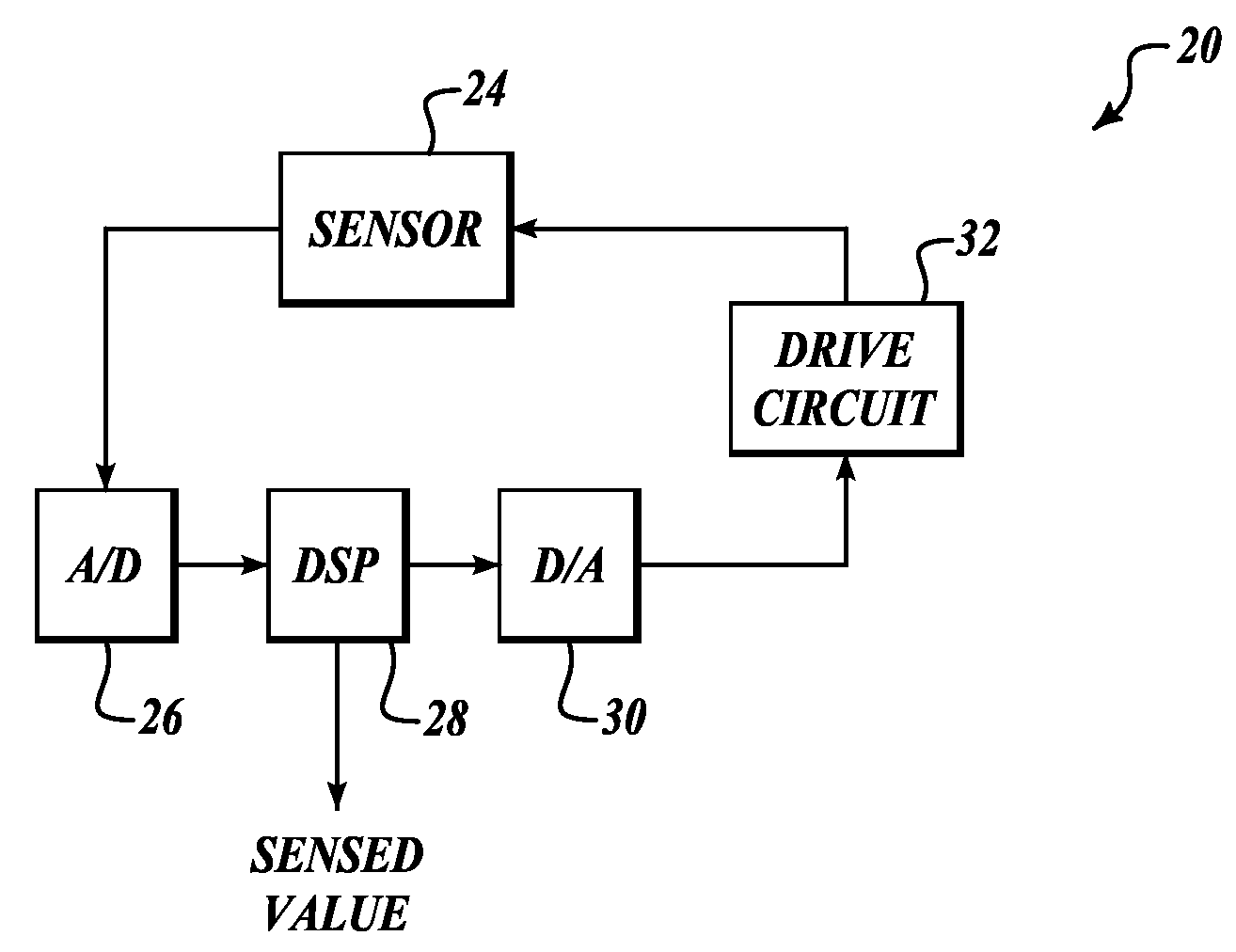
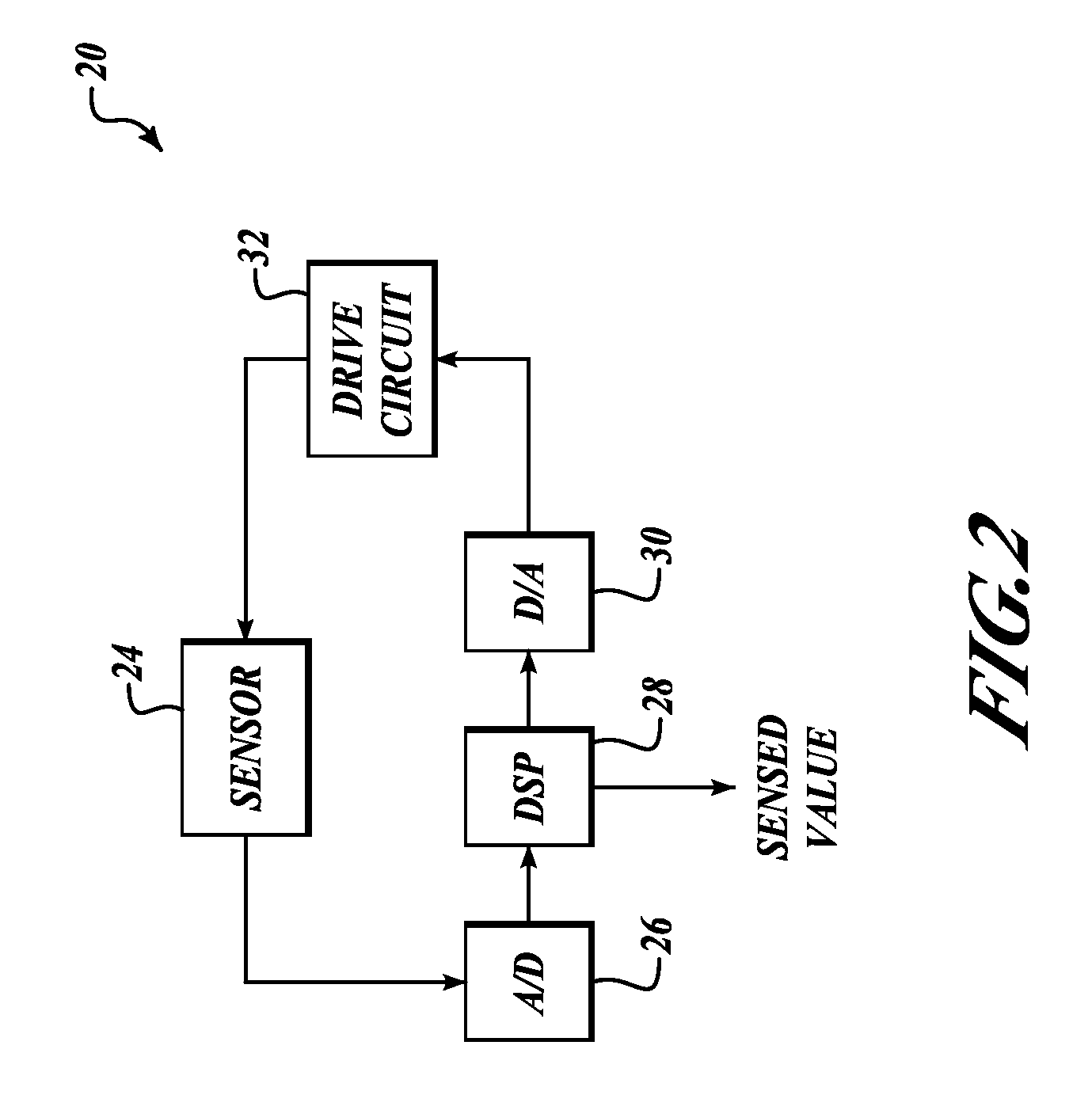
[0015]FIG. 2 illustrates an example sensor system 20 formed in accordance with an embodiment of the present invention. The system 20 includes an analog sensor 24, an analog-to-digital converter (ADC) 26, a digital signal processor 28, a digital-to-analog converter (DAC) 30, and a drive circuit 32. The sensor 24 may be any of a number of different types of sensors, for example fiber-optic sensors and gyros (e.g., FOGs). Many sensors, such as the fiber-optic gyro, employ a sinusoidal or square-wave modulation signal at a specific frequency to generate an output signal at the specific frequency that is indicative of the parameter to be sensed. One advantage of the modulation is to shift the measurement away from low frequency drift errors and 1 / f noise to a frequency that has no drift errors and lower noise. Furthermore, the modulation also allows the use of synchronous demodulation, such as a lock-in amplifier, which provides a means of extracting a very weak signal from noise.

[0016]T...


PUM


Abstract

Systems and methods for improving efficiency of a data converter. An example method generates a noise signal, alters the spectrum of the noise signal based on operation of an associated data converter, and supplies the altered spectrum noise signal to the associated data converter. The data converter is a digital-to-analog converter or an analog-to-digital converter. The altered spectrum noise signal is notched at frequencies of interest. The spectrum is altered by sending a signal generated by a random number generator to a delay device and adding the output of the delay device from the output of the random number generator. Also, the spectrum is altered by seeding first and second identical random number generators, delaying the operation of the first random number generator, and adding the output of the delayed first random number generator from the second random number generator.

Description

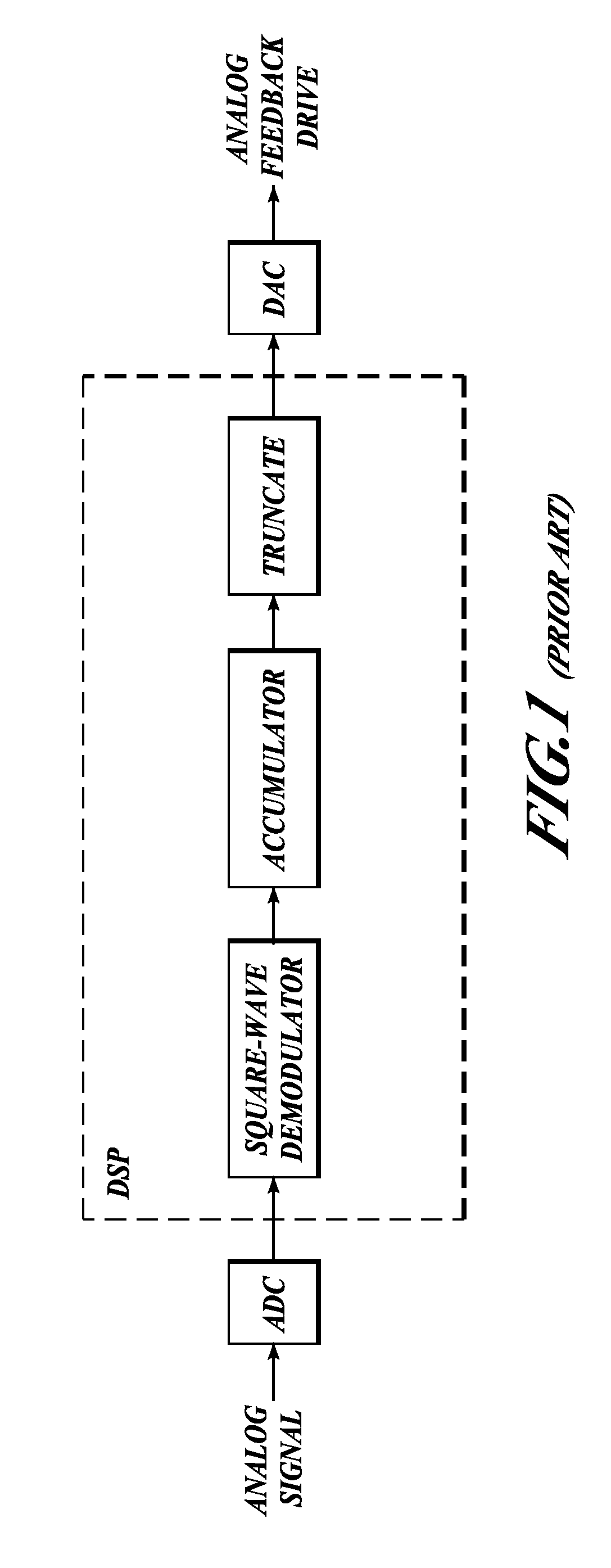
BACKGROUND OF THE INVENTION[0001]High performance systems (FIG. 1) employing analog-to-digital converters (ADCs) or digital-to-analog converters (DACs) and demodulators require high resolution converters. The performance of the systems can be limited by the resolution (number of bits) of the included converters. One solution is to increase the number of bits of the converter, which improves the resolution of the converters. However, this increases costs, power consumption, and size and results in slow performance.[0002]Another solution for improving converter resolution and differential linearity is to add noise and averaging. However, injecting noise into the converter increases undesirable noise in the system / sensor output.[0003]Therefore, there exists a need for improving the resolution of converters without adding significant cost or power consumption and without decreasing the speed of the converter.SUMMARY OF THE INVENTION[0004]The present invention provides systems and method...

Claims


Application Information

Patent Timeline
Patent Type & Authority Applications(United States)
IPC IPC(8): H03M1/20
CPCG06F7/588H03M1/661H03M1/201H03M1/0641
Inventor NEWLIN, MATTHEW P.STRANDJORD, LEE K.GREENING, THOMAS C.KEITH, GREGORY W.
Owner HONEYWELL INT INC
Learn More