Display apparatus and drive method thereof and electronic device

a technology of electronic devices and display devices, applied in static indicating devices, instruments, optics, etc., can solve the problems of affecting the luminance of light emitting devices, the threshold voltage of the transistor driving the light emitting device to fluctuate, and the picture quality is impaired, so as to minimize the fluctuation of the threshold voltage correcting operation and enhance the accuracy. , the effect of reducing the fluctuation

Inactive Publication Date: 2008-09-25
JOLED INC
View PDF4 Cites 153 Cited by
  • Summary
  • Abstract
  • Description
  • Claims
  • Application Information

AI Technical Summary

Benefits of technology

[0014]According to the first embodiment of the invention, the threshold voltage correcting operation has a compression process after the above-mentioned preparation process and energizing process. In the compression process, the reference potential applied to the gate after the energizing process is varied to compress the gate-to-source voltage higher than the voltage equivalent to the threshold voltage, thereby surely turning off the drive transistor. This configuration prevents a leak current from flowing in the drive transistor, thereby stably maintaining results of the threshold voltage correcting operation until later write and light emitting operations. In other words, the fluctuation of the threshold voltage correcting operation is minimized to significantly enhance the accuracy. Consequently, the light emitting luminance has little fluctuation to significantly enhance the quality of screen.
[0015]According to the second embodiment of the invention, the energizing process of the threshold voltage correcting operation is executed in a time division manner a plurality of times until the drive transistor is cut off. This configuration can give a sufficient energizing time, thereby surely allocating a voltage equivalent to the threshold voltage into the capacitor. In doing so, a difference is provided in the reference voltage level to be applied to the gate of the drive transistor between the preceding energizing process and the following energizing process. To be more specific, the reference voltage to be applied to the gate of the drive transistor in the following energizing process is set higher than that in the preceding energizing process. Thus, switching between the reference voltage levels in the energizing process executed in a time division manner can suppress the current leak of the drive transistor, eventually stabilizing the threshold voltage correcting operation and enhancing the accuracy thereof. Consequently, the fluctuation of the light emitting luminance of each pixel is minimized to improve the uniformity of screen.

Problems solved by technology

However, related-art active matrix planar self-luminous display apparatuses involve a problem of causing the threshold voltage of the transistor for driving light emitting devices to fluctuate due to process variation.
This characteristic fluctuation adversely affects light emitting luminance.
However, a current leak occurs on the drive transistor between the threshold voltage correcting operation and the light emitting operation, which causes the threshold voltage correction to be not necessarily executed correctly, thereby involving an error.
This error or fluctuation of the threshold voltage correction causes the unevenness in light emitting luminance, which in turn causes impaired picture quality.

Method used


Image

  • Display apparatus and drive method thereof and electronic device
  • Display apparatus and drive method thereof and electronic device
  • Display apparatus and drive method thereof and electronic device

Examples


Embodiment Construction

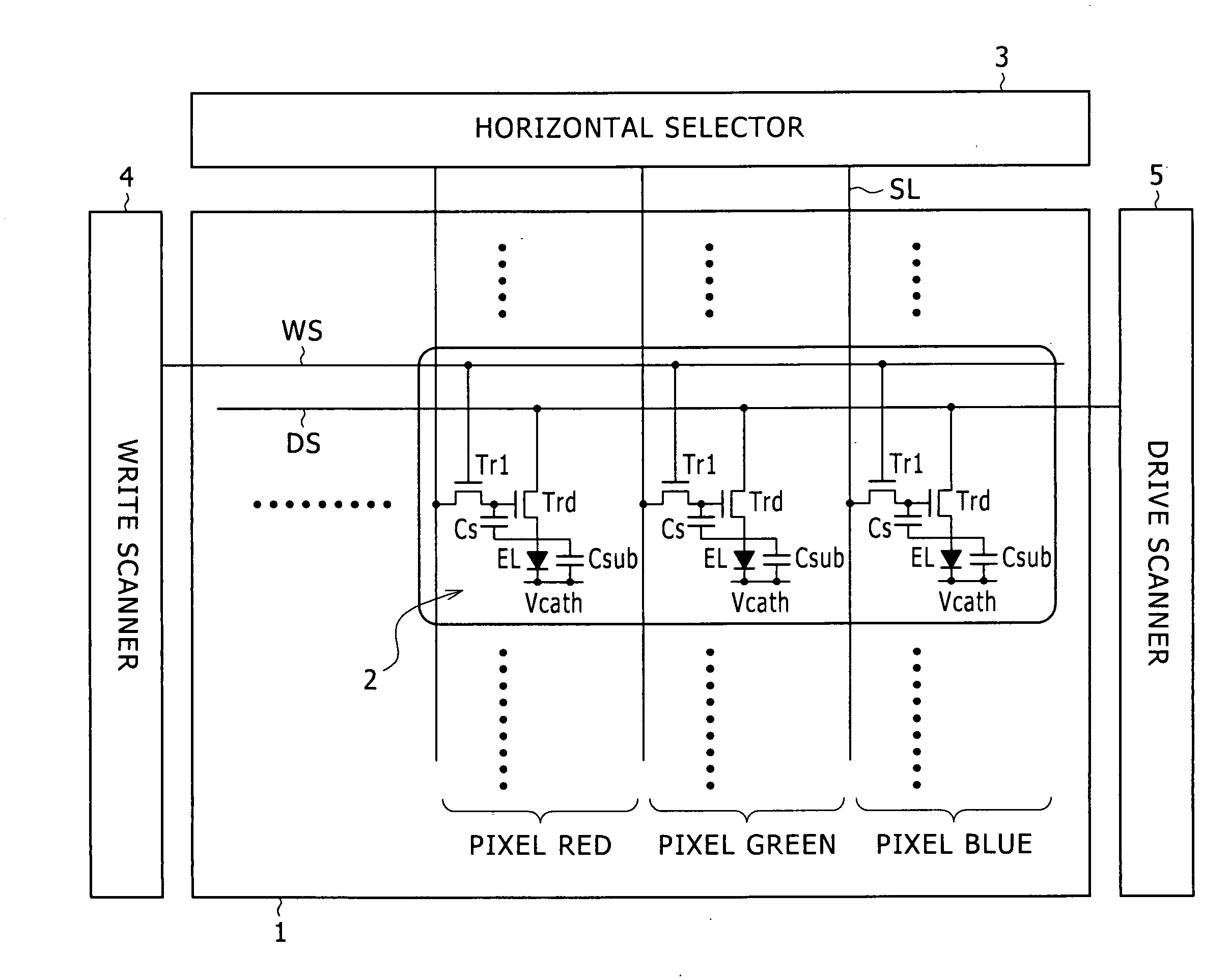
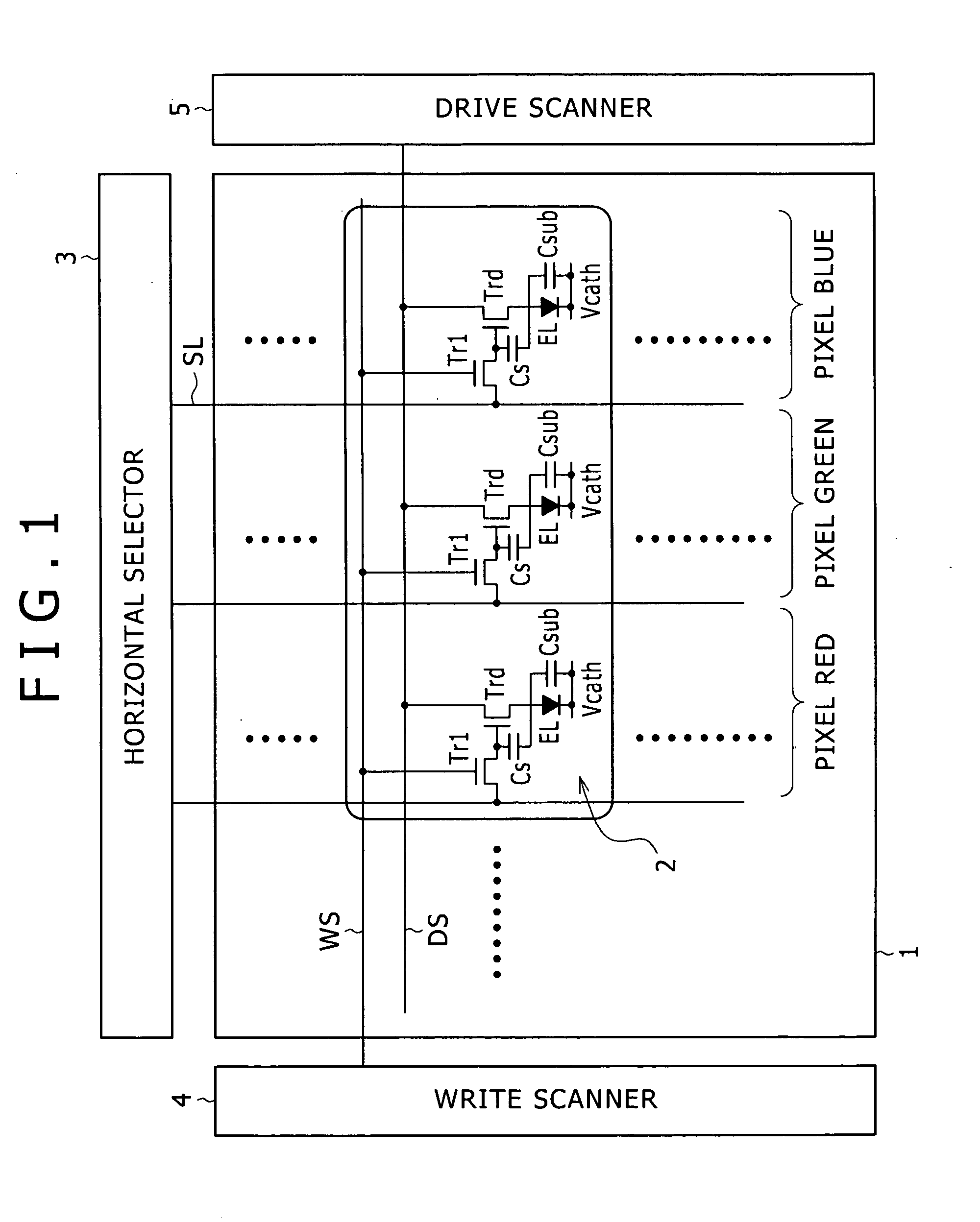
[0037]This invention will be described in further detail by way of embodiments thereof with reference to the accompanying drawings. Now, referring to FIG. 1, there is shown an overall configuration of a display apparatus practiced as one embodiment of the invention. As shown, the display apparatus is made up of a pixel array block 1 and a drive block configured to drive the pixel array block 1. The pixel array block 1 has write scan lines WS arranged in row, signal lines SL arranged in column, pixels 2 each arranged in row at each intersection between the write scan line WS and the signal lines SL, and power supply lines DS each arranged for each row of pixels 2. The drive block has a write scanner 4 for sequentially supplying control signals to the write scan lines to sequentially scanning pixels 2 on a row basis, a drive scanner 5 for supplying a supply voltage switching between high and low potentials for each power supply line DS in synchronization with this line sequential scan...


PUM


Abstract

Disclosed herein is a display apparatus including a pixel array section and a drive section. The pixel array section has power supply lines, scan lines arranged in row, signal lines arranged in column, and pixels arranged in matrix at intersections of each of the scan lines and each of the signal lines. The drive transistor is connected at one of a pair of current terminals to the light emitting device and at the other of the pair of current terminals to the power supply line. The drive section supplies a control signal to each scan line and a video signal to each signal line to drive each pixel, executing a threshold voltage correcting operation, a write operation, and a light emitting operation.

Description

CROSS REFERENCES TO RELATED APPLICATIONS[0001]The present invention contains subject matter related to Japanese Patent Application JP 2007-074985 filed in the Japan Patent Office on Mar. 22, 2007, the entire contents of which being incorporated herein by reference.BACKGROUND OF THE INVENTION[0002]1. Filed of the Invention[0003]The present invention relates to a display apparatus of active matrix type based on light emitting devices used as pixels and the drive method thereof. The present invention also relates to an electronic device based on this display apparatus.[0004]2. Description of the Related Art[0005]Recently, planar self-luminous display apparatuses based on organic EL (ElectroLuminescence) devices have been increasingly under development. The organic EL device is a light emitting device based on a phenomenon in which light is emitted when an electric field is impressed upon an organic thin film. The organic EL device can be driven on less than 10 V of applied voltage, so ...

Claims


Application Information

Patent Timeline
Patent Type & Authority Applications(United States)
IPC IPC(8): G06F3/038H05B44/00
CPCG09G3/3233G09G2300/0819G09G2310/0297G09G2310/0256G09G2300/0842G09G3/30G02F1/133H05B33/12G09G3/32
Inventor MINAMI, TETSUOTOMIDA, MASATSUGUIIDA, YUKIHITOUCHINO, KATSUHIDE
Owner JOLED INC
Why Eureka
Try Eureka