Method of manufacturing color filter

Inactive Publication Date: 2008-09-25
AU OPTRONICS CORP
View PDF5 Cites 11 Cited by
  • Summary
  • Abstract
  • Description
  • Claims
  • Application Information

AI Technical Summary

Benefits of technology

[0027]The present invention utilizes an ink jet printing process to form color filter films having identical color but different thickness in the single sub pixel area of a color filter. Therefore, uneven image color in the same sub pixel area can be improved wh

Problems solved by technology

Consequently, a color mismatch of the image displayed by the reflective area and the transmissive area in a single sub pixel area may occur.
In reality, the idea of obtaining color filter films of different thickness by adjusting the degree of exposure is not easy to implement.
In general, the photoresist material under the semi-transparent part 150b either completely reacts or does not react with light after being illuminated during the exposure and therefore the degree

Method used


Image

  • Method of manufacturing color filter
  • Method of manufacturing color filter
  • Method of manufacturing color filter

Examples


Example

First Embodiment

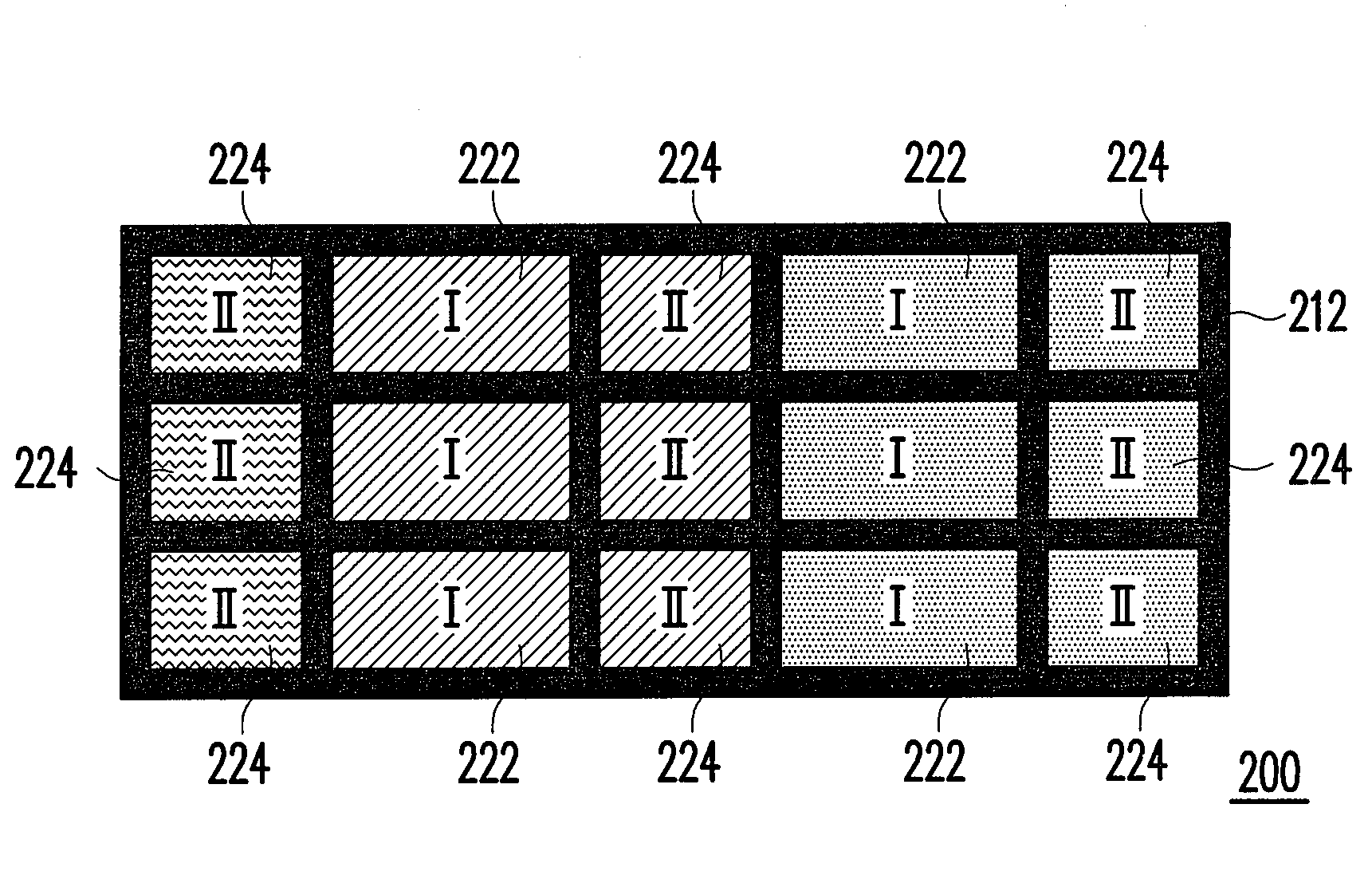
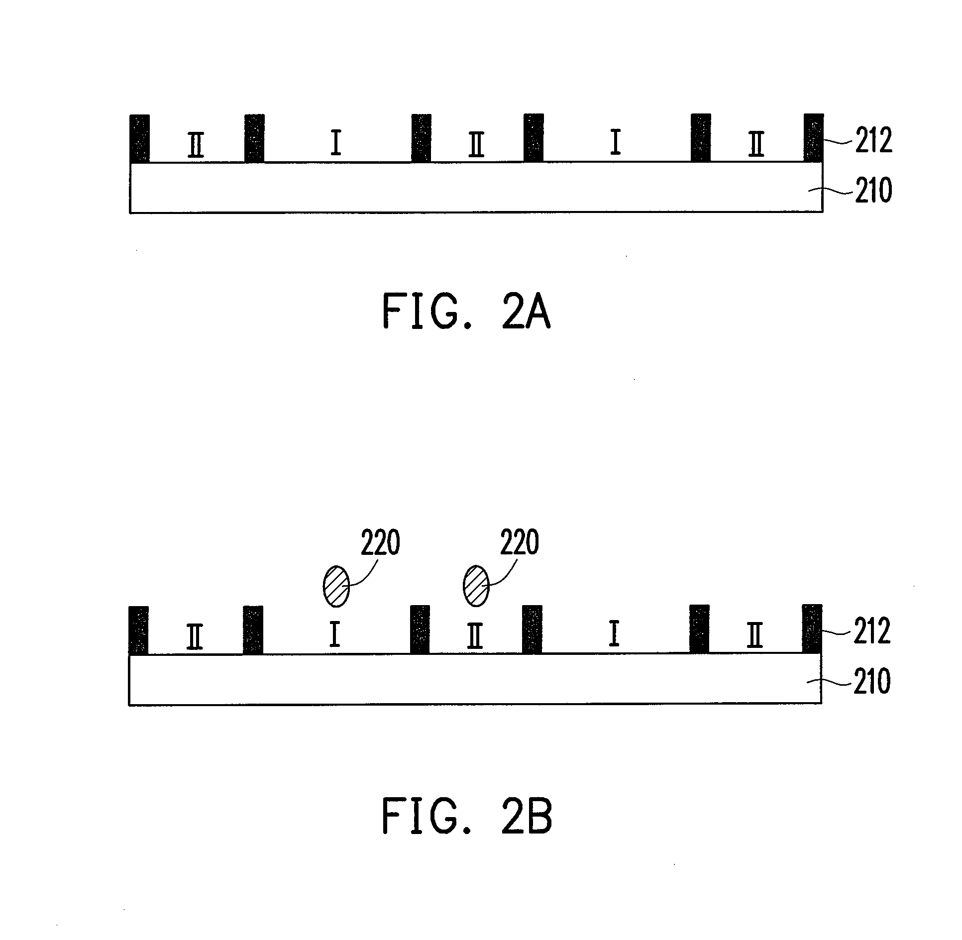
[0035]FIGS. 2A to 2C are side views showing a method of fabricating a color filter according to a first embodiment of the present invention. First, as shown in FIG. 2A, a substrate 210 is provided and then a partition, for example, a photoresist partition, a set of embankments or a black matrix is formed on the substrate 210. In the present embodiment, a black matrix 212 is used as an example. The black matrix 212 defines a plurality of first color filter areas I and a plurality of second color filter areas II corresponding to the first color filter areas I on the substrate 210. In general, the substrate 210 is a transparent substrate such as a glass substrate or an amorphous silicon substrate, and the black matrix is a black matrix made of resin, metal or a combination of resin and metal, for example.

[0036]Next, as shown in FIG. 2B, an ink jet printing process is performed to fill the interior of the first color filter areas I and the interior of corresponding secon...

Example

Second Embodiment

[0044]FIGS. 3A to 3D are side views showing a method of fabricating a color filter according to a second embodiment of the present invention. First, as shown in FIG. 3A, a substrate 310 is provided and then a partition, for example, a photoresist partition, a set of embankments or a black matrix is formed on the substrate 310. In the present embodiment, a black matrix 312 is used as an example. The black matrix 312 defines a plurality of sub pixel areas P (only one is shown in the present embodiment). Furthermore, each sub pixel area P has a first color filter area I and a second color filter area II outside the first color filter area I. More specifically, the substrate 310 is a transparent substrate, and the black matrix 312 is a non-transparent black matrix made of resin or metal, for example.

[0045]Next, as shown in FIG. 3B, a first color filter film 322 is formed in each of the first color filter areas I by performing a first ink jet printing process. More speci...


PUM


Abstract

A method of manufacturing a color filter is provided. First, a substrate is provided and then a partition, for example a black matrix, is formed on the substrate. The black matrix defines a plurality of first color filter areas and a plurality of second color filter areas corresponding to the first color filter areas on the substrate. Thereafter, a first color filter film and a second color filter film are formed in each of the first color filter areas and each of the second color filter areas corresponding thereto, respectively, such that a color filter is provided. The thickness of the first color filter film differs from the thickness of the second color filter film. Thus, images displayed by a transflective liquid crystal display with the aforementioned color filter have even colors.

Description

CROSS-REFERENCE TO RELATED APPLICATION[0001]This application claims the priority benefit of Taiwan application serial no. 96109887, filed Mar. 22, 2007. All disclosure of the Taiwan application is incorporated herein by reference.BACKGROUND OF THE INVENTION[0002]1. Field of the Invention[0003]The present invention generally relates to a method of manufacturing a color filter, in particular, to a method of manufacturing a color filter applied to a transfiective liquid crystal display.[0004]2. Description of Related Art[0005]Because a liquid crystal display is a non self-illuminating display, a liquid crystal display panel must have a light source (for example, a back light source, a front light source or an external light source) for displaying images. According to the manner in which the light source is utilized, liquid crystal displays can be classified into transmissive liquid crystal displays, transflective liquid crystal displays and reflective liquid crystal displays. At presen...

Claims


Application Information

Patent Timeline
IPC IPC(8): B41M3/00G03F1/00
CPCG02F1/133371G02F1/133512G03F7/0007G02F1/133516G02F1/133514
Inventor CHEN, WEN-LUNGLEE, SHU-CHINTSAI, FU-CHUANWANG, WEI-YALIN, YONG-MAOTSAO, CHUN-CHIEH
Owner AU OPTRONICS CORP
Why Eureka
Try Eureka