
On-vehicle camera lens glass material and on-vehicle camera lens

a technology for camera lenses and glass materials, which is applied in the field of on-vehicle camera lens glass materials and on-vehicle camera lenses, can solve the problems of difficult to configure an imaging lens suitable, lens damage or eroded, and concern about lens surface deterioration and metamorphosis, and achieve excellent environmental resistance, scratch resistance, and chemical durability. excellent

Active Publication Date: 2008-09-25
HOYA CORP
View PDF11 Cites 21 Cited by
  • Summary
  • Abstract
  • Description
  • Claims
  • Application Information

AI Technical Summary

Benefits of technology

The invention provides an on-vehicle camera lens glass material that is resistant to acid rain and chemicals, has high refractive index, and is suitable for use in severe environments. The material has a hardness sufficient to scratch, is resistant to deterioration from ultraviolet rays, and has a low solarization. The material can be made into an optical device such as an imaging lens for an on-vehicle camera. The technical effects of the invention include improved durability and optical performance of the on-vehicle camera lens.

Problems solved by technology

However, it is difficult to configure an imaging lens suitable for the requirement by the plastic lens and the low refractive glass lens.
In such an imaging lens mounted in the on-vehicle camera, unlike an imaging lens of general camera, there is a possibility that the lens is damaged or eroded by shock, wind pressure, and dust while vehicle is running.
In addition, there is also concern about lens surface deterioration and metamorphosis that is caused by acid rain and chemicals such as a cleanser and a wax used at the time of car washing.
Further, when oil, dust, and coarse particulates are attached on a surface of the imaging lens, sometimes the lens surface may be blurred as time elapses, and when a contamination is in contact with the lens surface for a long time, sometimes the lens surface may metamorphose.
In addition, when the camera is mounted on the front side of a vehicle body, there is concern about lens deterioration caused by heat generated from an engine and by nitrous oxide contained in gas exhausted from other vehicles which are running ahead of the vehicle.
Further, the lens is frequently exposed under a severe environment where, for example, direct sun light including ultraviolet rays is irradiated on the lens for a long time.
Accordingly, when the imaging lens mounted in the on-vehicle camera is made of plastic material or optical glass material used in a general imaging lens, there is concern that enough durability is not secured.
The reason is that plastic material and glass material, which has low glass transition temperature suitable for a precision press forming process that enables mass production of an aspheric surface lens, have low hardness and are easily scratched.
In addition, plastic material has lower ultraviolet resistance than glass material, and is easily deteriorated when ultraviolet rays are irradiated thereon for a long time.
However, when the protective member is installed, there is concern that the imaging view angle of the lens is restricted, and it becomes difficult to sufficiently enlarge the imaging view angle.

Method used


Image

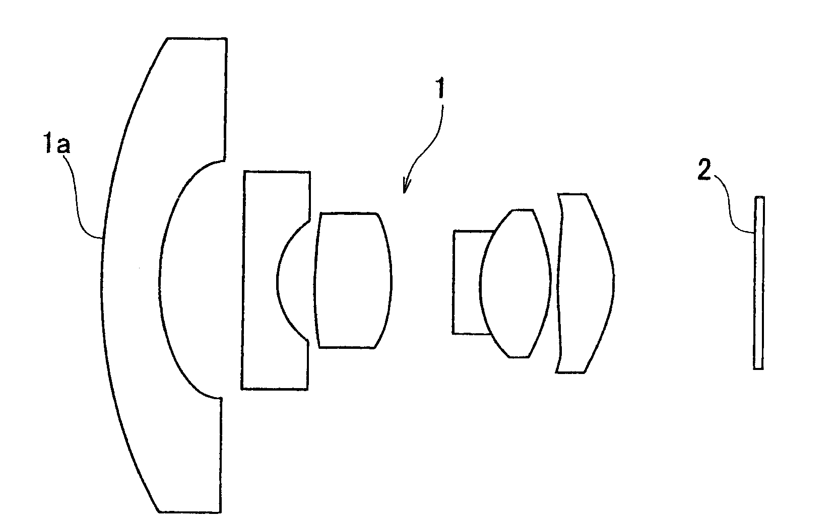
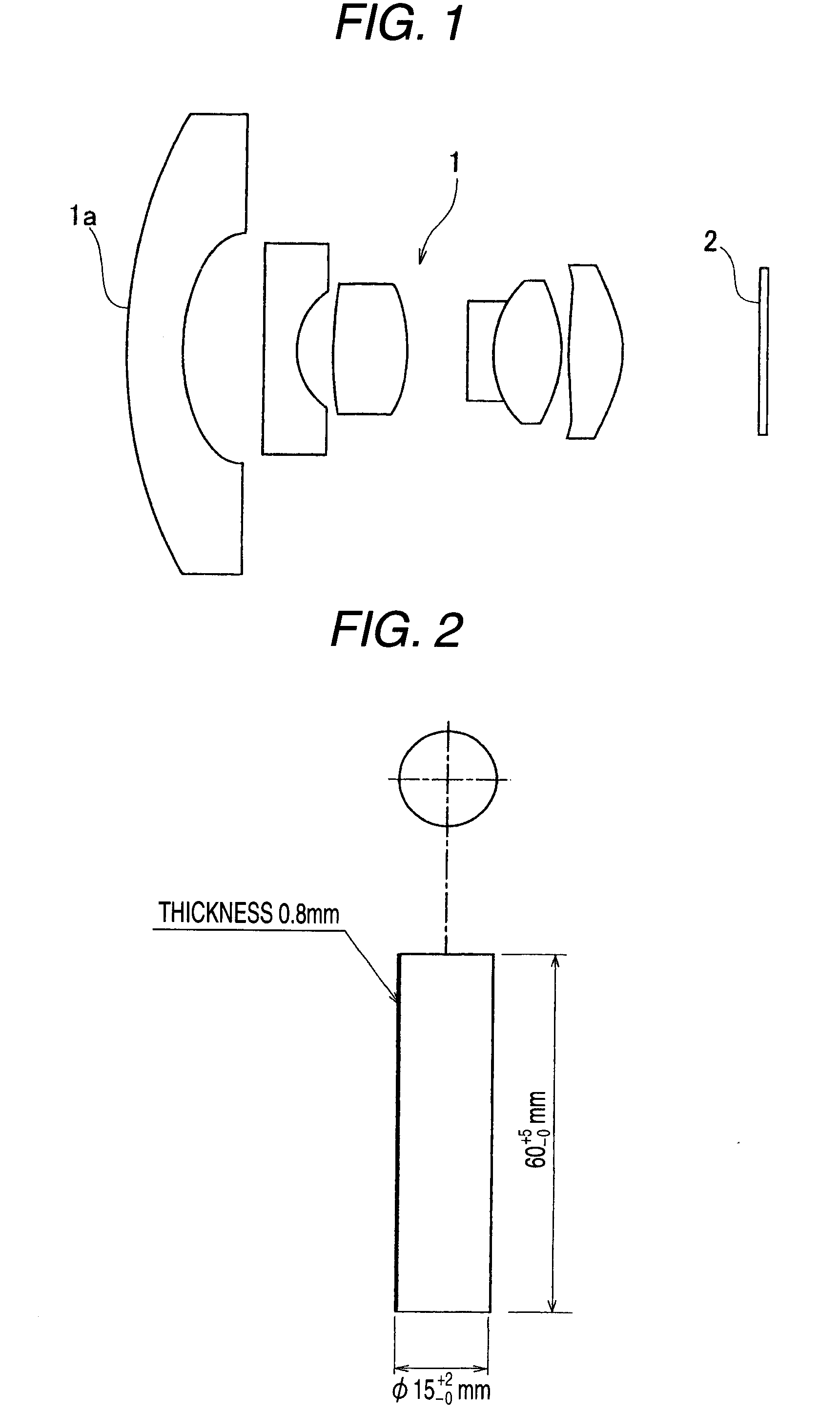
  • On-vehicle camera lens glass material and on-vehicle camera lens
  • On-vehicle camera lens glass material and on-vehicle camera lens

Examples


examples

[0230]Hereinafter, examples of the invention will be described.

examples 1 to 5

and a comparative example of the on-vehicle camera lens glass material according to the invention are provided by the inventors as shown in the following Table 1.

[0231]

TABLE 1ComparativeExample 1Example 2Example 3Example 4Example 5ExampleSiO230.07.07.07.043.05.0B2O32.010.013.08.03.024.0Li2O1.00.00.00.08.00.0CaO26.00.03.00.018.00.0BaO0.00.011.015.00.00.0ZnO0.05.04.01.00.023.0La2O33.041.038.034.03.038.0Gd2O30.010.00.00.00.00.0Y2O30.04.00.00.00.00.0ZrO210.06.06.07.08.04.0Nb2O519.02.05.08.07.06.0Ta2O50.015.00.00.00.00.0TiO29.00.013.020.010.00.0SiO2 + ZrO240.013.013.014.051.09.0Nb2O5 + TiO228.02.018.028.017.06.0Nb2O5 + TiO2 + Ta2O528.017.018.028.017.06.0nd1.8071.8851.8052.0001.7021.786νd33.040.731.325.440.043.9specific3.55.44.64.72.94.4gravityα (×10−7 ° C.−1)886088879871DW0.01% (1)0.01% (1)0.02% (1)0.01% (1)0.02% (1)0.02% (1)DA0.02% (1)0.10% (1)0.15% (1)0.02% (1)0.03% (1)0.47% (3)Hk 685 (7) 730 (7) 630 (6) 600 (6) 670 (7) 690 (7)solarization0.8%0.5%0.8%0.8%0.8%0.5%(α: average linear expa...


PUM

PropertyMeasurementUnit
refractive indexaaaaaaaaaa

Abstract

An on-vehicle camera lens glass material satisfies at least one of conditions in which a measurement result in water resistance based on a powder method prescribed by Japanese Optical Glass Industrial Standard is 1st Class, a measurement result in Knoop hardness based on a measurement method prescribed by Japanese Optical Glass Industrial Standard is 6th Class or higher, a measurement result in solarization based on a measurement method prescribed by Japanese Optical Glass Industrial Standard is 2% or less, and a measurement result in average linear expansion coefficient based on a measurement method prescribed by Japanese Optical Glass Industrial Standard is 100×10−7° C.−1 or less.

Description

BACKGROUND OF THE INVENTION[0001]1. Field of the Invention[0002]The present invention relates to an on-vehicle camera lens glass material used for an optical device such as an imaging lens mounted in an on-vehicle camera and to the on-vehicle camera lens.[0003]2. Description of Related Art[0004]Conventionally, in order to eliminate driver's blind spots while driving a vehicle, there has been proposed a method of installing an on-vehicle camera on a vehicle. Specifically, by installing a camera for imaging the rear and the side of a vehicle on the vehicle itself, an image taken by the camera is displayed on a position where a driver can check the image by his / her own eyes. Therefore, it is possible to eliminate the blind spots.[0005]In view of a low price and light weight, an optical device made of plastic material or low refractive glass material is broadly used for an optical device such as an imaging lens mounted on the on-vehicle camera, as described in Japanese Patent Unexamined...

Claims


Application Information

Patent Timeline
Patent Type & Authority Applications(United States)
IPC IPC(8): G02B27/00C03C3/062C03C3/076C03C3/095C03C3/06
CPCB60R1/00C03C3/097C03C3/068B60R2300/802
Inventor HACHITANI, YOICHITACHIWANA, KAZUO
Owner HOYA CORP
Learn More