Extensible micro-mobility wireless network architecture

a wireless network and micro-mobility technology, applied in the field of wireless communication systems, can solve the problems of difficulty in vertical roaming, difficulty in navigating varying quality of service, difficulty in navigating different roaming policies and prices,

Active Publication Date: 2008-09-25
CLEARWIRE IP HLDG
View PDF9 Cites 75 Cited by
  • Summary
  • Abstract
  • Description
  • Claims
  • Application Information

AI Technical Summary

Problems solved by technology

Many technical issues make vertical roaming difficult.
In fact, many of these technical issues relate to horizontal roaming between different operators using the same technology.
These technical issues include what happens when a user roams onto a network having Quality of Service (“QoS”) offerings that are different from (higher or lower than) the QoS offerings of the network to which the user was previously connected, how to navigate varying qualities of service, and perhaps most difficult of all, how to navigate different roaming policies and prices.
Despite undergoing 12 years of development, MIP has yet to see widespread deployments and adoption by end-users.
Unfortunately, this model does not capture many aspects of common, real world deployments operated by wireless network providers.
One of the largest problems with this architecture is that even though the R6 and R4 interfaces provide full mobility within the ASN without MIP, the FA and HA routers 330 and 332, respectively, integral to the MIP design, are based on the fundamental assumption that CSN anchored mobility is a requirement.
The Layer 3 IP connections (lines “L3”), which couple the FA routers 3301-330c of the ASNs 110,112, and 310, respectively, to the HA router 332, may traverse long distances before reaching the Internet 140, which negatively impacts performance and increases costs.
Such WAN connections may be very expensive.
As the above discussion illustrates, MIP relies on complex Layer 3 router architectures that are unwieldy and expensive to deploy.
Further, MIP introduces many issues to network design and deployment that burden a network operator.
In theory, IPv6 solves many problems with CMIPv4; however, IPv6 has yet to be widely deployed and many complex issues exist with transitioning large networks from I...

Method used


Image

  • Extensible micro-mobility wireless network architecture
  • Extensible micro-mobility wireless network architecture
  • Extensible micro-mobility wireless network architecture

Examples


Embodiment Construction

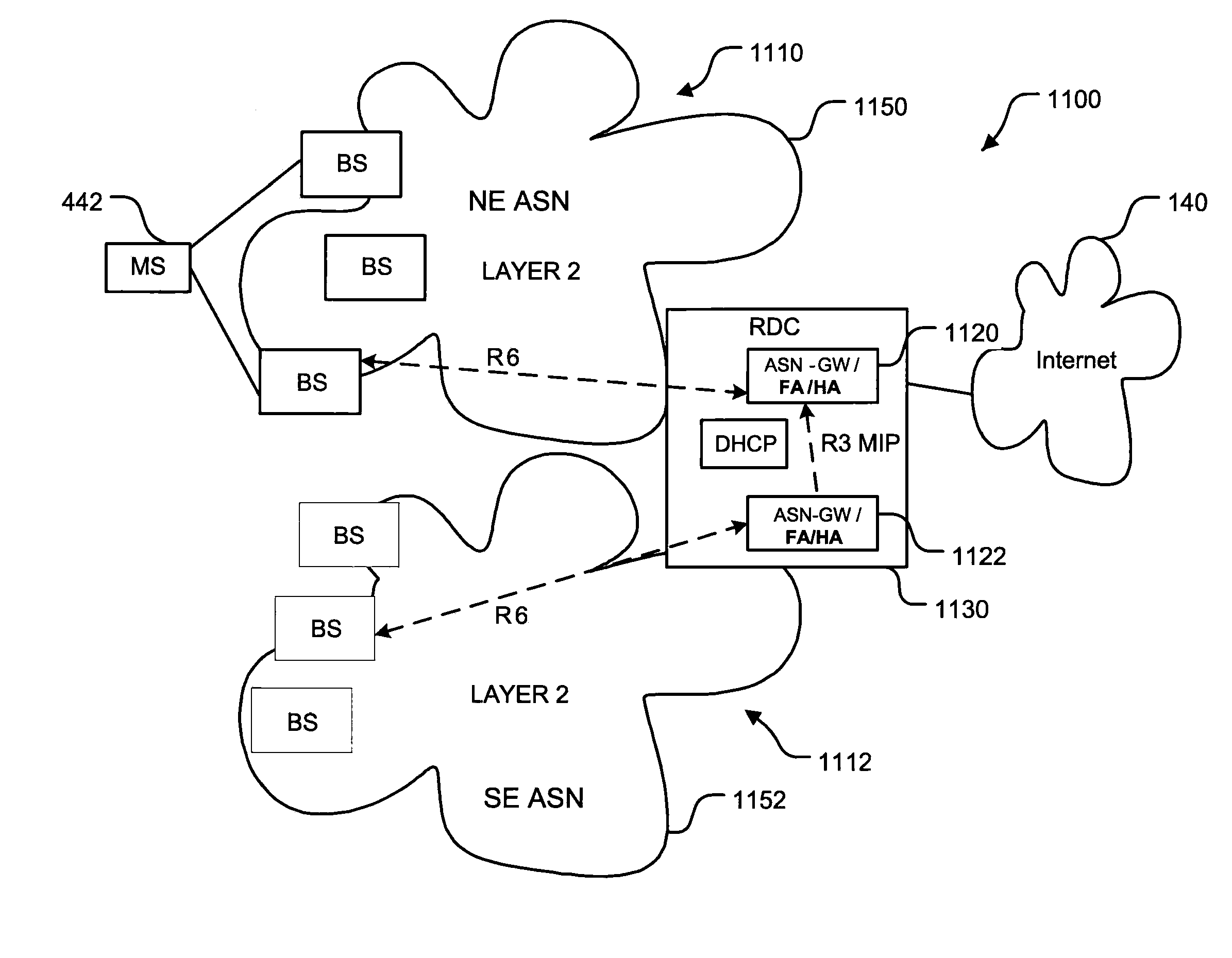
[0065]The following list of abbreviations may be useful in understanding the technology discussed herein:[0066]3G Third Generation (Cellular)[0067]AAA Authentication, Authorization and Accounting[0068]AN Access Network[0069]AP Access Point[0070]ARP Address Resolution Protocol[0071]ASN Access Service Network (Same as AN)[0072]ASN-GW Access Service Network Gateway (router)[0073]BS Base Station[0074]CMIP Client Mobile IP[0075]CSN Core Services Network[0076]DHCP Dynamic Host Configuration Protocol[0077]DNS Domain Name Service[0078]FA Foreign Agent[0079]HA Home Agent[0080]IEEE Institute of Electrical and Electronic Engineers[0081]IETF Internet Engineering Task Force[0082]IOT Inter Operability Tests[0083]IP Internet Protocol[0084]L2 Layer 2[0085]L3 Layer 3[0086]LAN Local Area Network[0087]MAC Media Access Control[0088]MAN Metro Area Network[0089]MEF Metro Ethernet Forum[0090]MIP Mobile IP[0091]MPLS Multi Protocol Label Switching[0092]MS Mobile Station[0093]NAP Network Access Provider[0094...


PUM


Abstract

A network having an access service network (“ASN”) configured to provide full mobility to mobile stations located within a service area. The ASN includes a Layer 2 or data link layer network that is larger, incorporates more nodes, or carries more data communications than Layer 2 networks incorporated in prior art ASNs. Data communications to and from the mobile stations are routed inside the ASN across the Layer 2 network which transports the data communication using a Layer 2 protocol. If the network includes another ASN located adjacent to the first ASN, the two ASNs may communicate directly with one another over a Layer 2 connection. If the network includes another ASN that is not adjacent to the first, Mobile Internet Protocol components may be included in the ASNs and configured to provide mobility between ASNs.

Description

CROSS REFERENCE TO RELATED APPLICATION(S)[0001]This application claims the benefit of U.S. Provisional Application No. 60 / 896,748, filed Mar. 23, 2007.BACKGROUND OF THE INVENTION[0002]1. Field of the Invention[0003]The present invention is directed generally to wireless communication systems.[0004]2. Description of the Related Art[0005]The terms roaming and mobility are typically used synonymously to refer to the general concept of a wireless subscriber being able to move around on a network instead of being chained to a single location. Starting from a high-level perspective, the specific functionalities related to how and where a user may roam are primarily determined by (1) ownership of the network, (2) the technology used by the network, (3) network attachment mechanisms (i.e., the means by which a user stays attached or re-attaches to the network), and (4) what type of service(s) must be supported during network re-attachment. By applying different requirements and definitions ...

Claims


Application Information

Patent Timeline
IPC IPC(8): H04L12/28H04W8/08H04W8/26H04W36/00H04W40/00H04W80/00H04W80/04H04W88/08
CPCH04L29/12028H04L61/103H04W8/087H04W88/08H04W40/00H04W80/04H04W8/26
Inventor GELBMAN, PETERWINTER, MARK ADRIAN
Owner CLEARWIRE IP HLDG
Why Eureka
Try Eureka