Nuclear fuel assembly with an advanced spacer grid

a fuel assembly and spacer technology, applied in nuclear engineering problems, nuclear elements, greenhouse gas reduction, etc., can solve the problems of general removal of oxide layers by abrasion, and achieve the effect of reducing spring stiffness

Inactive Publication Date: 2008-09-25
WESTINGHOUSE ELECTRIC CORP
View PDF10 Cites 17 Cited by
  • Summary
  • Abstract
  • Description
  • Claims
  • Application Information

AI Technical Summary

Benefits of technology

[0016]In a second embodiment of the invention, the hard dimples employed by the prior art to support the rods are eliminated and eight appropriately shaped cantilevered springs on each rod cell are provided. Each of the springs provides a relatively large line of contact with a fuel rod to provide an adequate force with low contact pressure, rod support through life. The low contact pressure is not enough to cause generalized removal of the oxide layer by abrasion, even when due to dimensional changes or small relative movement between the rod and the support points. Desirably, two cantilevered springs are provided per side of each fuel rod cell. The shape of each of the cantilevered springs is such that when a uniform pressure is applied which corresponds to the contact pressure with the fuel rod, the spring surface is in theoretical contact with the rod along a vertical line parallel to the axis of the fuel rod. This requires that the undeflected spring is slightly curved along its length. In the compressed condition, the spring area where the rod contact takes place is bent around a vertical bend line along the full lengths of the spring and way from the surface of the rod, so that the rod is in contact with two essentially convex surfaces per side defining two narrow lines of contact. The leading edge of the springs is further sent away around a horizontal bend line which, along with the vertical b end line, for a three-dimensional curved quasi-spherical surface. Desirably, to control the stiffness of the spring, shallow elongated horizontal indentations may be stamped on the straps extending along a portion of the length of the springs to add to the springs stiffness or vertical slots may be incorporated where a reduction in spring stiffness is required.
[0017]In another embodiment, conventional mixing vanes can be used within the vicinity of each fuel rod. The mixing vanes, positioned at the intersection of the straps, preferably have a small hole to allow welding of the strap intersection. In another embodiment and in addition to or instead of conventional mixing vanes at at least some of the strap intersection surrounding each rod, the strap configuration of this invention allows insertion of additional mixing devices, such as twisted ribbon inserts, inside the open cells between fuel rod cells. The ribbons are welded in place inside the grid cells between rods.

Problems solved by technology

The low contact pressure is not enough to cause generalized removal of the oxide layer by abrasion, even when due to dimensional changes or small relative movement between the rod and the support points.

Method used


Image

  • Nuclear fuel assembly with an advanced spacer grid
  • Nuclear fuel assembly with an advanced spacer grid
  • Nuclear fuel assembly with an advanced spacer grid

Examples


Embodiment Construction

[0030]Nuclear fuel spacer grids are used in fuel assemblies to position nuclear fuel rods. Accurately positioning nuclear fuel rods is critical to assure proper nuclear and thermo-hydraulic performance of the nuclear core of a reactor. An ideal nuclear fuel spacer grid should:

[0031]1. be simple and inexpensive to manufacture;

[0032]2. permit fuel rod reconstitution and easy loading of the fuel rods;

[0033]3. maintain fuel assembly geometry over the lifetime of the fuel assembly;

[0034]4. be of a lower pressure drop design, yet promote coolant mixing and heat transfer; and

[0035]5. be low neutron absorbers.

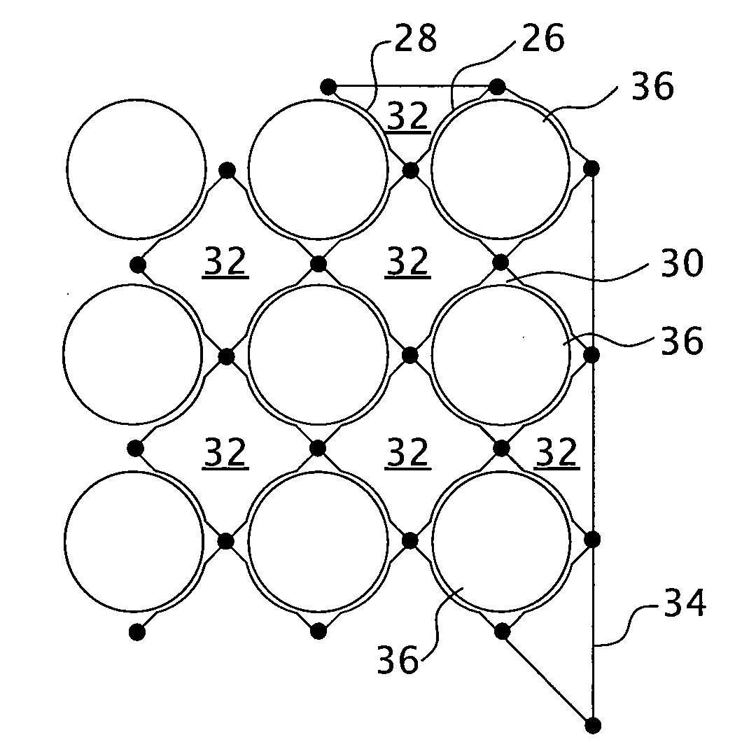
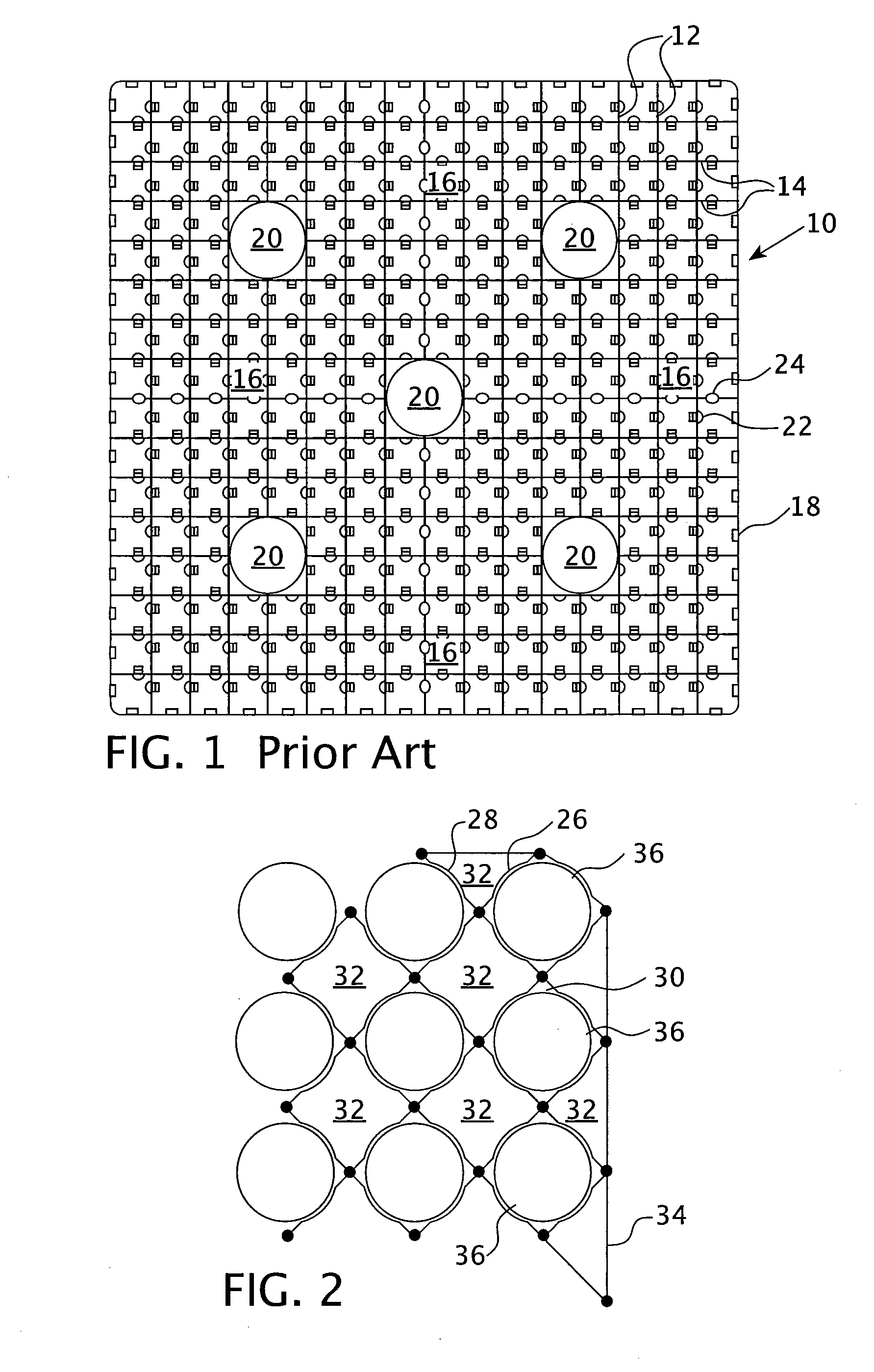
[0036]Many conventional spacer grids are composed of straight grid straps that are interleaved together to form an egg-crate configuration having a plurality of roughly square cells, many of which support the fuel rods. An example of such conventional fuel grid 10 can be found in FIG. 1. A spaced parallel array of grid straps 12 of equal length are positioned orthogonally to a second p...


PUM


Abstract

An improved nuclear fuel assembly having elongated grid straps curved in a substantially undulating wave pattern along their axial length and interleaved together to form an egg-crate configuration having a plurality of roughly square cells that support fuel rods and guide tube thimbles. The cells that support fuel rods have their outer walls curved outward to increase the contact area around the fuel rod cladding The interior straps are on a diagonal with regard to a peripheral strap and at least one cell adjacent each fuel rod cell is left empty for the unobstructed flow of coolant. Additional coolant mixing devices can be added to the empty cells. The walls of each fuel rod cell are devoid of dimples and, in one embodiment, springs.

Description

BACKGROUND OF THE INVENTION[0001]1. Field of the Invention[0002]The present invention relates generally to nuclear reactors, and more particularly, to a pressurized water nuclear reactor having a fuel assembly with an improved grid.[0003]2. Description of the Related Art[0004]In most pressurized water nuclear reactors (PWR), the reactor core is comprised of a large number of elongated fuel assemblies. These fuel assemblies typically include a plurality of fuel rods held in an organized array by a plurality of grids spaced axially along the fuel assembly length and attached to a plurality of elongated thimble tubes of the fuel assembly. The thimble tubes typically receive control rods or instrumentation therein. Top and bottom nozzles are on opposite ends of the fuel assembly and are secured to the ends of the thimble tubes that extend slightly above and below the ends of the fuel rods.[0005]The grids, as is known in the relevant art, are used to precisely maintain the spacing and su...

Claims


Application Information

Patent Timeline
Patent Type & Authority Applications(United States)
IPC IPC(8): G21C3/34
CPCG21C3/352G21C3/3563G21Y2002/201G21C3/322G21Y2002/302G21Y2004/30Y02E30/40G21Y2002/206Y02E30/30
Inventor REPARAZ, ADOLFOMCCREARY, DAVID M.
Owner WESTINGHOUSE ELECTRIC CORP
Why Eureka
Try Eureka