
Two Stage Detection for Photographic Eye Artifacts

Active Publication Date: 2008-09-25
FOTONATION LTD
View PDF49 Cites 87 Cited by
  • Summary
  • Abstract
  • Description
  • Claims
  • Application Information

AI Technical Summary

Benefits of technology

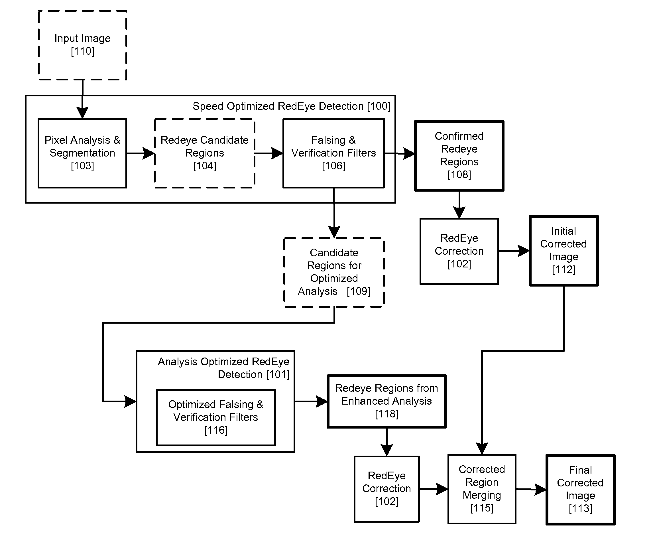
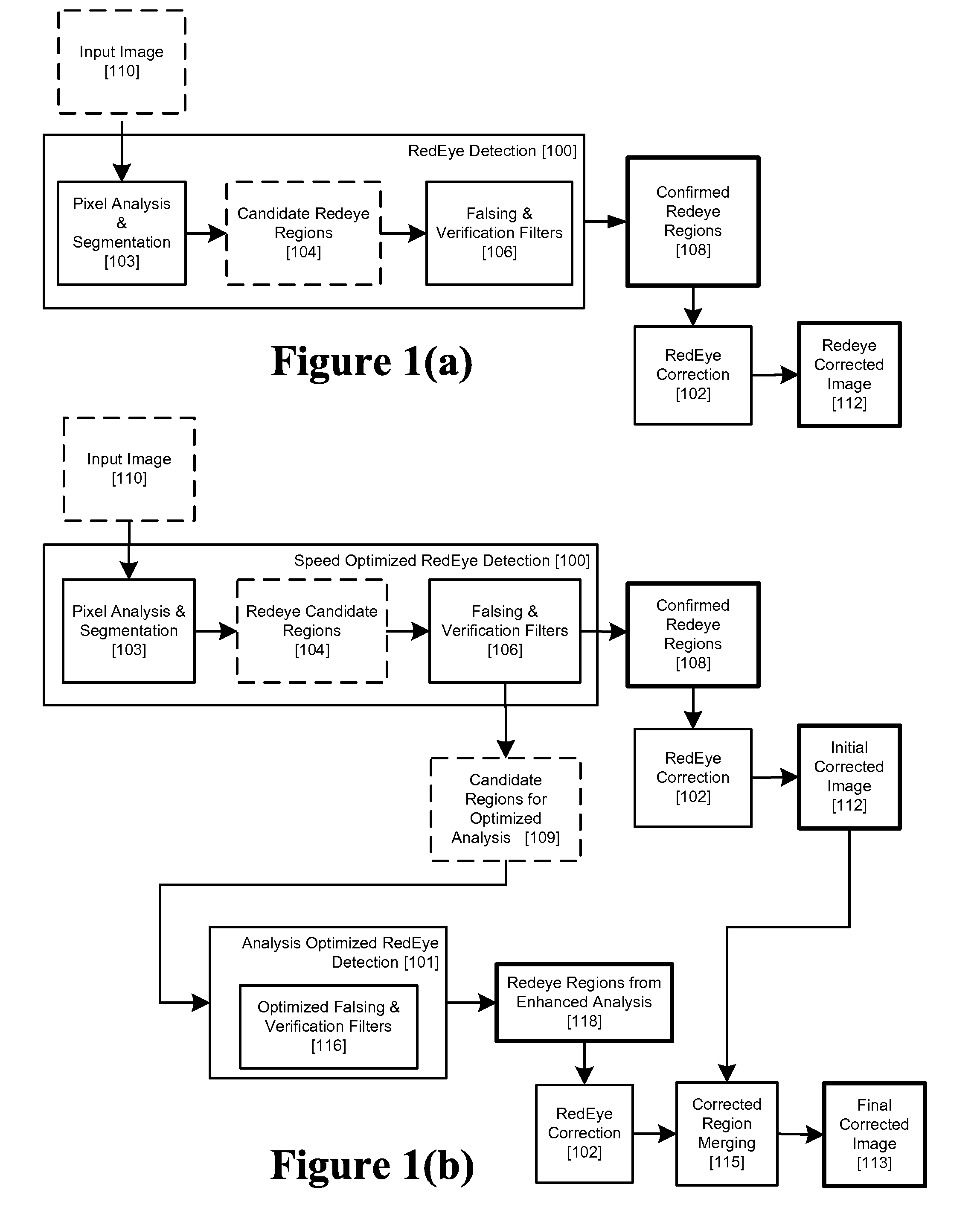
[0054]In the embodiments above, the speed optimized redeye detection 100 is preferably applied to a sub-sampled input image. The confirmed redeye regions 108 from this speed optimized redeye detection 100 are passed to a redeye correction module 102 / 102a. The corrected redeye image 112 can be displayed on a low-resolution viewing screen of a digital camera immediately after the image acquisition process providing the user with a redeye corrected image almost instantly. However, although this initial corrected image 112 may be adequately corrected, for example, where it is a portrait-style image in which a face occupies most of an image or where large high probability red-eye regions exist, it may not be adequately corrected for images including a large groups of persons, where the candidate redeye regions are smaller or less certain. Accordingly, the second analysis optimized redeye filtering process 101 is implemented after image acquisition but prior to final image 113 display on a larger viewer, or image printing. We remark that one advantage of the present invention is that the analysis optimized redeye detection 101 and correction 102 processes may be delayed until such high resolution viewing or printing is desired by the end user.
[0055]It should be noted that in the embodiments of FIGS. 2(a) and 2(b), the sub-sampled versions of the main image or well as uncorrected full size versions of the main image may be provided directly from main image acquisition device hardware 402 rather than needing to explicitly sub-sample a decoded full size main image.
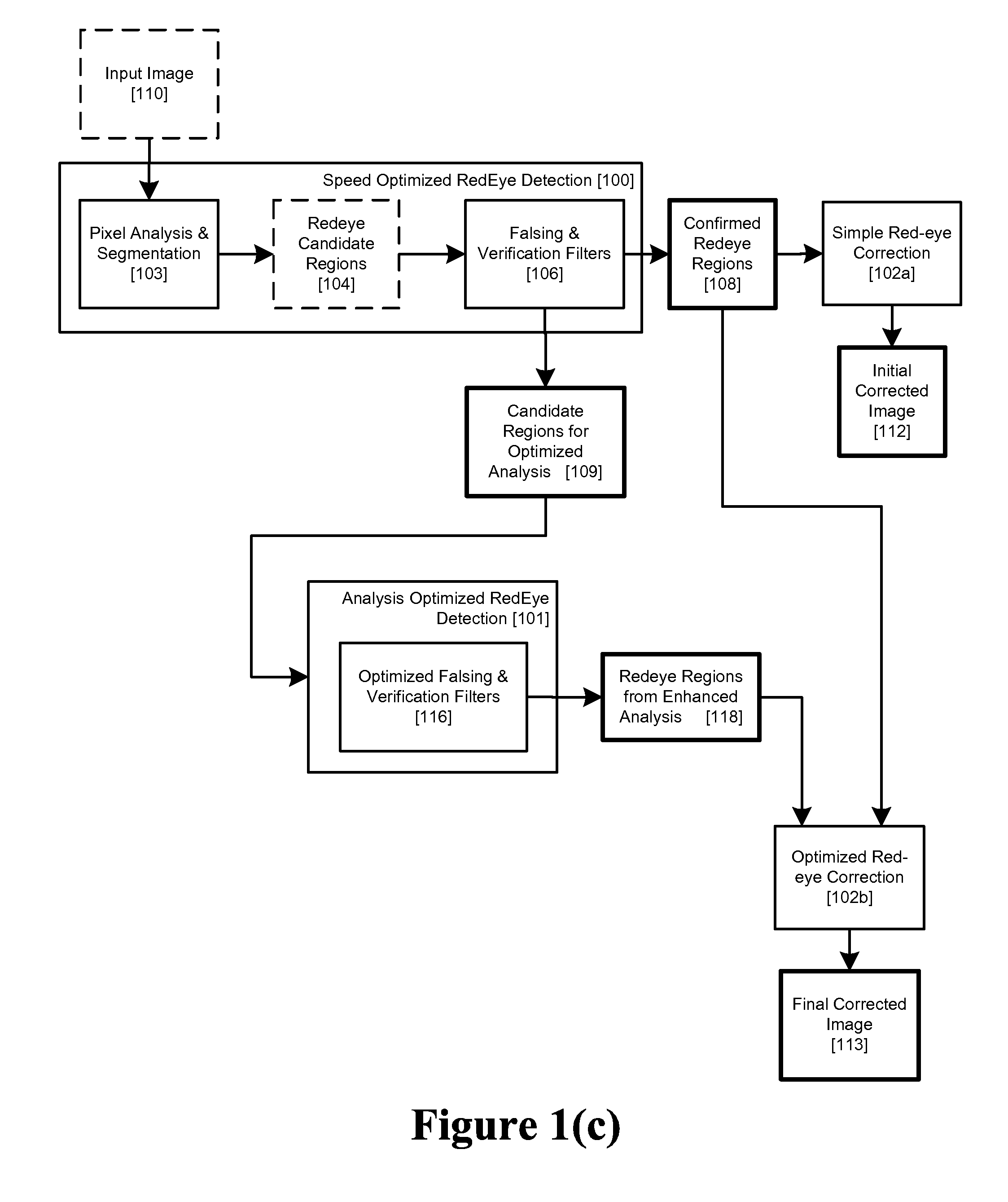
[0056]As in the case, of FIG. 1(c), it will be seen that image correction need not be performed on images within the acquisition chain and can in fact be performed in the background on acquired images for which speed optimised redeye detection has been performed in the acquisition chain. This is advantageous in many image acquisition appliances where image compression is often implemented in hardware as part of the main image acquisition chain 401. In this embodiment, only the detection process is actually performed in the acquisition chain. A speed optimized correction or a full analysis optimized redeye filter may be subsequently selected in playback mode either based on a predetermined setting within the camera, or on a user selection at the time of image playback / viewing.
[0057]In the embodiment of FIG. 3(a), an acquired raw image 402 is partially processed 404 before being provided to DCT compression block 408-1. This block essentially provides a sub-sampled version of the acquired image and, although not shown, this can be provided to the image store 410 as explained above. A speed optimized redeye detector 428 is then applied to the partially compressed DCT block image and DCT red-eye candidate regions both corrected and suspected uncorrected regions are output for storage in the store 410. An advantage of applying speed optimised correction at DCT block level, rather than at the pixel level, is that the need for an explicit image subsampling step is avoided, yet the benefits of applying redeye analysis to a sub-sampled image as detailed in the prior art cited herein are retained.
[0058]The regions output by the DCT prefilter 428, incorporated in the main image acquisition chain 401, can advantageously allow much of the DCT block stream to be bypassed without being processed when an image is subsequently corrected by a filter such as a background filter module 426. This allows either much faster or more detailed analysis and filtering of the DCT blocks which are determined to require processing by an analysis optimized redeye filter 406. Those skilled in the art will realize that further embodiments are possible which separate aspects of both the DCT prefilter and the otherwise conventional type redeye filter 406 between the main image acquisition chain, 401 and a background redeye detection and correction process 426.
[0059]FIG. 3(b) shows in more detail the operation of the redeye DCT prefilter 428. This particular example illustrates how the DCT prefilter can integrate with the main image acquisition, processing and compression chain, 402, 404 and 408 of FIG. 3(a). The DCT image to be filtered is first loaded into memory 902 after which the main DCT prefilter 428 is applied. This has three main steps: firstly the DCT blocks of the image are scanned 904 and the relevant DCT coefficients are extracted. Depending on the sophistication of the filter, only the DC components of each DCT block may be utilized in the subsequent analysis. Alternatively, some of the AC components may be extracted in order to allow some texture or sharpness / blur determination as part of the prefilter operation.

Problems solved by technology

In general, face-detection-based automatic redeye reduction techniques have high computation and memory resource requirements.
In addition, most of the face detection algorithms are only able to detect faces that are oriented in an upright frontal view; these approaches cannot detect faces that are rotated in-plane or out-of-plane with respect to the image plane.
Evidently such a redeye filter must compromise its overall performance in terms of accuracy of detection of redeye defects and quality of image correction.
However there are some drawbacks to this approach.
Firstly, images will be displayed on the acquiring device, immediately after acquisition, with uncorrected redeye defects; and, when images are accessed in playback mode, there will be a further delay while images are post-processed before an image can be displayed.
Both drawbacks would create a negative impression on end users.
Further, as practically all digital cameras store images using lossy compression techniques there are additional disadvantages with respect to image quality as images must be decompressed and recompressed in order to perform the redeye detection and correction processes in playback or background modes.
Such loss of image quality may not become apparent until later when a user wishes to print an image and it is too late to reverse the process.

Method used


Image

  • Two Stage Detection for Photographic Eye Artifacts
  • Two Stage Detection for Photographic Eye Artifacts
  • Two Stage Detection for Photographic Eye Artifacts

Examples


Embodiment Construction

[0040]The detection of red-eye defects is enhanced in digital images for embedded image acquisition and processing systems. A two-stage redeye filtering process is provided whereby a speed optimized filter performs the initial segmentation of candidate redeye regions and optionally applies a speed-optimized set of falsing / verification filters to determine a first set of confirmed redeye regions for correction. Some of the candidate regions which are rejected during the first stage are recorded and re-analyzed during a second stage by an alternative set of analysis-optimized filters to determine a second set of confirmed redeye regions.

[0041]In another embodiment, the first set of confirmed redeye regions may be passed through the stage-two analysis-optimized filters.

[0042]In an another embodiment the second stage filter may incorporate an enhanced correction filter which may be optionally applied to the first set of confirmed redeye regions.

[0043]A two-stage redeye filter is impleme...


PUM


Abstract

The detection of red-eye defects is enhanced in digital images for embedded image acquisition and processing systems. A two-stage redeye filtering system includes a speed optimized filter that performs initial segmentation of candidate redeye regions and optionally applies a speed-optimized set of falsing / verification filters to determine a first set of confirmed redeye regions for correction. Some of the candidate regions which are rejected during the first stage are recorded and re-analyzed during a second stage by an alternative set of analysis-optimized filters to determine a second set of confirmed redeye regions.

Description

PRIORITY AND RELATED APPLICATIONS[0001]This application claims the benefit of priority to U.S. provisional patent application No. 60 / 892,884, filed Mar. 5, 2007, which is incorporated by reference. This application is also a Continuation-in-Part (CIP) of U.S. patent application Ser. No. 11 / 462,035, filed Aug. 2, 2006 and Ser. No. 11 / 282,954, filed Nov. 18, 2005 and published as US2007 / 0116379, which are incorporated by reference.FIELD OF THE INVENTION[0002]The present invention relates to digital image processing, and more particularly to a method and apparatus for detection and correction of red-eye defects and other artifacts in an acquired digital image.BACKGROUND[0003]Redeye is the appearance of an unnatural reddish coloration of the pupils of a person appearing in an image captured by a camera with flash illumination. Redeye is caused by light from the flash reflecting off blood vessels in the person's retina and returning to the camera.[0004]A large number of image processing ...

Claims


Application Information

Patent Timeline
IPC IPC(8): G06K9/40
CPCG06K9/0061G06V40/193
Inventor PRILUTSKY, YURYSTEINBERG, ERANCORCORAN, PETERPOSOSIN, ALEXEIBIGIOI, PETRONELCIUC, MIHAI
Owner FOTONATION LTD
Learn More