Method of Sterilization and Apparatus Therefore

Inactive Publication Date: 2008-09-25
YUYAMA MFG CO LTD +1
View PDF9 Cites 49 Cited by
  • Summary
  • Abstract
  • Description
  • Claims
  • Application Information

AI Technical Summary

Benefits of technology

[0048]Greater sterilization effects are produced by the sterilization method and apparatus of the present invention through the combined use of hydrogen peroxide, ozone and plasma. Moreover, not only is the residual hydroge

Problems solved by technology

However, although all these conventional sterilization apparatuses are constructed so as not to leave residual harmful gas, their sterilization effects have not been adequate.
The problem is that when the c

Method used


Image

  • Method of Sterilization and Apparatus Therefore
  • Method of Sterilization and Apparatus Therefore
  • Method of Sterilization and Apparatus Therefore

Examples


first embodiment

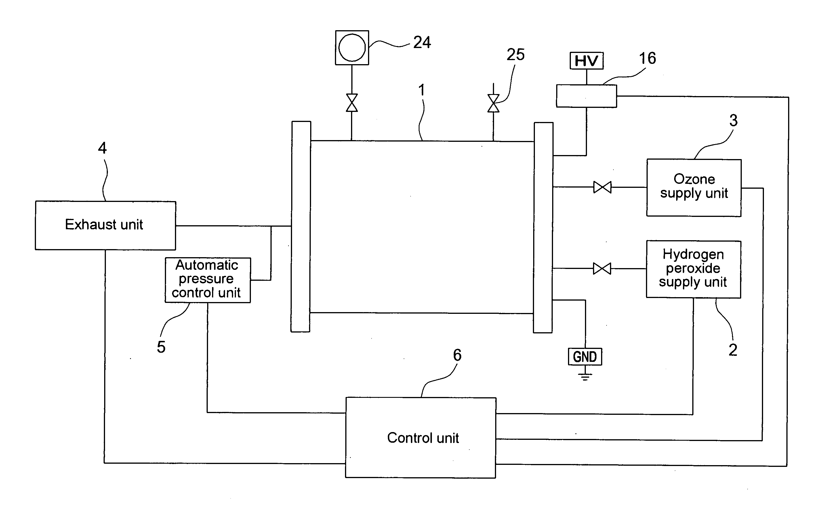
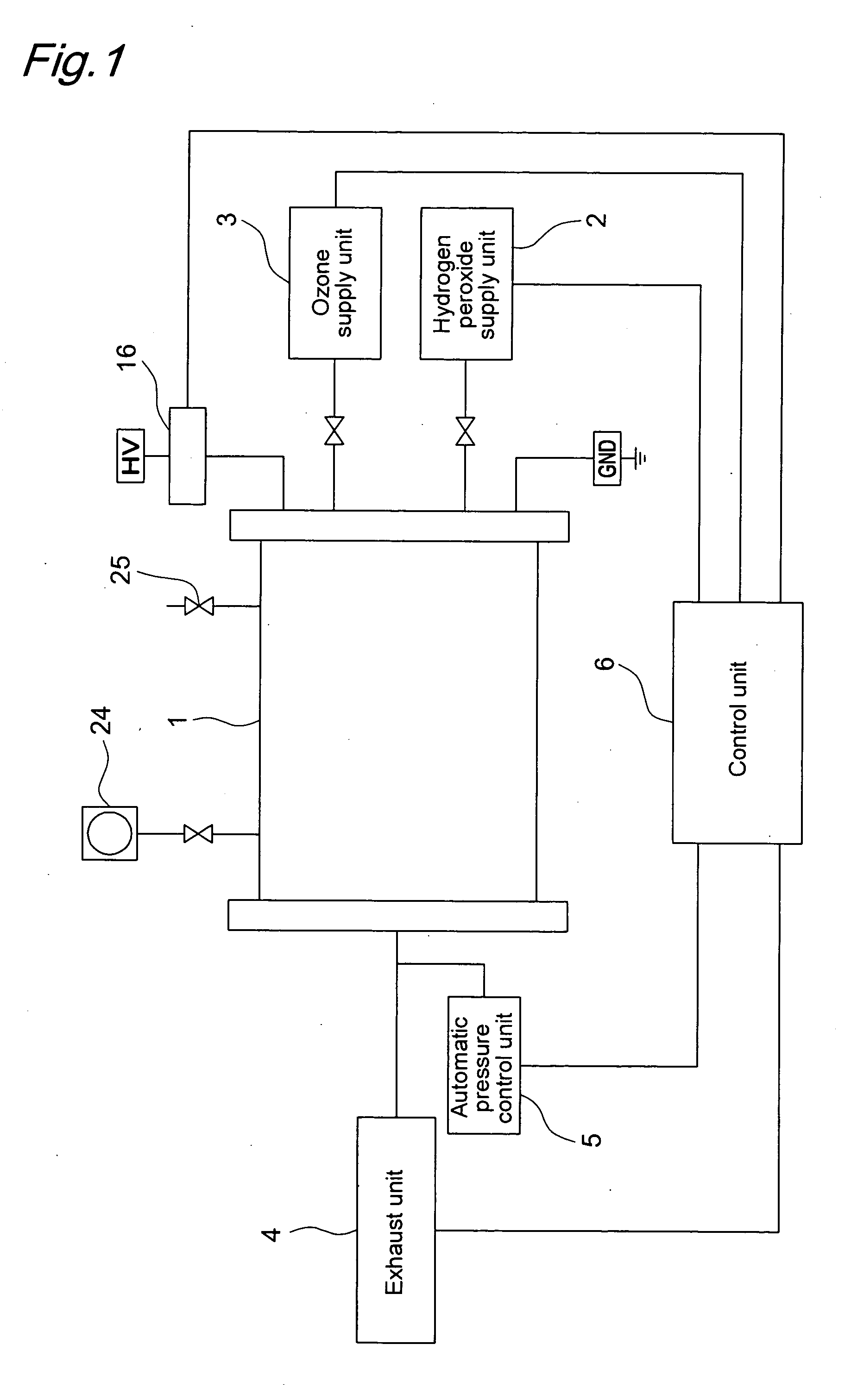
[0093]FIG. 1 shows a sterilization apparatus according to the present invention. This sterilization apparatus comprises chamber 1, hydrogen peroxide supply unit 2, ozone supply unit 3, exhaust unit 4, automatic pressure control unit 5, and control unit 6.

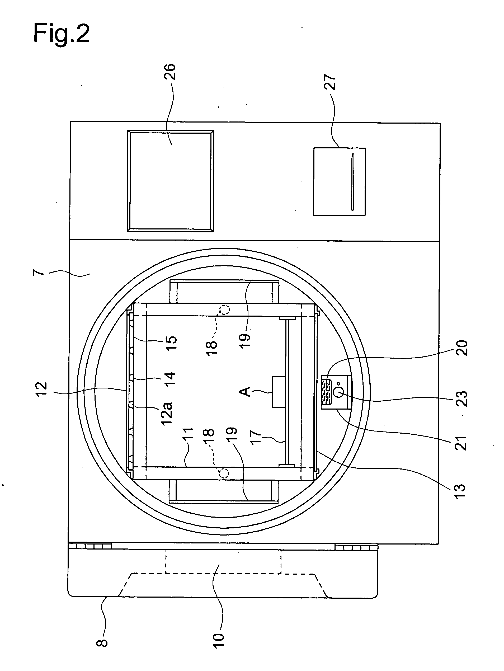
[0094]Chamber 1 has the cylindrical shape as shown in FIGS. 2 and 3, with flanges 7 attached to both ends. Door 8 is attached to the front flange 7 so as to open and close freely. Closed cover 9 is attached to the back flange 7. Door 8 is equipped with glass window 10, which allows the interior to be checked visually.

[0095]Chamber 1 contains frame 11, with rectangular high-voltage electrode 12 and low-voltage electrode 13 arranged on the top and bottom of frame 11. Dielectric 15 (insulating body) with holes 14 formed therein (5 mm in diameter in this embodiment a fixed pitch (20 mm to 100 mm) as shown in FIG. 4 is affixed to the surface of high-voltage electrode 12 which faces low-voltage electrode 13. The part exposed through holes...

second embodiment

[0135]Operation of sterilization apparatus of the second embodiment having the above configuration will be explained with reference to the flow chart of FIG. 15 and the pressure change diagram of FIG. 16.

[0136]Exhaust unit 4A is operated in Step S101 to depressurize chamber 1. When the pressure inside chamber 1 has reached a specific pressure such as 3.8 Torr (500 Pa) for example in Step S102, hydrogen peroxide supply unit 2A is operated to supply hydrogen peroxide inside chamber 1 in Step S103. Once the pressure inside chamber 1 has risen to a specific pressure such as 22.6 Torr (3013 Pa) for example due to the supply of hydrogen peroxide, ozone supply unit 3A is operated in Step S104 to supply ozone inside chamber 1. Once the pressure inside chamber 1 has risen to about 700 Torr (93325 Pa) for example due to the supply of ozone, this state is maintained for a specific time in Step S105 to disperse the sterilization gas inside chamber 1 and sterilize the object to be sterilized (ma...


PUM


Abstract

The present invention provides a harmless sterilization method and sterilization apparatus which provide adequate sterilization effects without residual gas. The method comprises: a sterilization step in which a chamber containing an object to be sterilized is depressurized; a hydrogen peroxide supply step in which hydrogen peroxide is supplied into the chamber; an ozone supply step in which ozone is supplied into the chamber; a sterilization step in which the hydrogen peroxide and ozone supplied inside the chamber are dispersed to sterilize the object to be sterilized; an exhaust step in which gas inside the chamber is exhausted; and a plasma generation step in which plasma is generated inside the chamber to break down hydrogen peroxide and ozone remaining near the object to be sterilized, and radicals which promote sterilization are generated.

Description

TECHNICAL FIELD[0001]The present invention relates to a sterilization method and apparatus for sterilizing medical instruments and the like.BACKGROUND ART[0002]Conventional sterilization apparatuses include those combining hydrogen peroxide with plasma, those combining ozone with plasma and those combining hydrogen peroxide with ozone.[0003]As an example of sterilization with hydrogen peroxide plus plasma, patent document 1 below describes a sterilization method which includes a step of placing an object to be sterilized in a chamber, a step of keeping the object in contact with hydrogen peroxide for a time sufficient for the hydrogen peroxide to become closely involved with the object, a step of generating plasma around the object, and a step of holding the object in the plasma for a time required for sterilization.[0004]Patent document 2 below describes a sterilization method that includes a step of bringing an object to be sterilized into contact with hydrogen peroxide, a step of...

Claims


Application Information

Patent Timeline
IPC IPC(8): A61L2/14A61L2/20
CPCA61L2/14A61L2202/24A61L2/208A61L2/202A61L2202/122
Inventor MIZUNO, AKIRAYUYAMA, HIROYUKISHIRAHARA, YOSHINORI
Owner YUYAMA MFG CO LTD
Why Eureka
Try Eureka