Processes for Separating Chlorine from Chlorine-Containing Gas Streams

a technology of chlorine-containing gas and process, which is applied in the direction of dispersed particle separation, halogen/halogen-acid, inorganic chemistry, etc., can solve the problems of harmful substances or inert waste gas components, and achieve the effect of reducing the operating cost of chlorine-containing absorption and simplifying the work-up

Inactive Publication Date: 2008-09-25
BAYER MATERIALSCIENCE AG
View PDF8 Cites 4 Cited by
  • Summary
  • Abstract
  • Description
  • Claims
  • Application Information

AI Technical Summary

Benefits of technology

[0006]One object of the present invention concerns the provision of processes which can simplify the work-up of chlorine-containing waste gas streams and which can avoid the need for absorption processes as described above.
[0007]Various embodiments of processes according to the present invention, by contrast, allow chlorine contained in a waste gas to be obtained in a more economical manner, as a result of which it is possible to dispense with downstream chemical absorption of the chlorine, and / or the operating costs of such absorption are reduced significantly.

Problems solved by technology

Furthermore, depending upon the particular jurisdiction and the scope of legislation, such waste gas components can be regarded as inert or as harmful substances.

Method used


Image

  • Processes for Separating Chlorine from Chlorine-Containing Gas Streams
  • Processes for Separating Chlorine from Chlorine-Containing Gas Streams
  • Processes for Separating Chlorine from Chlorine-Containing Gas Streams

Examples


example 1

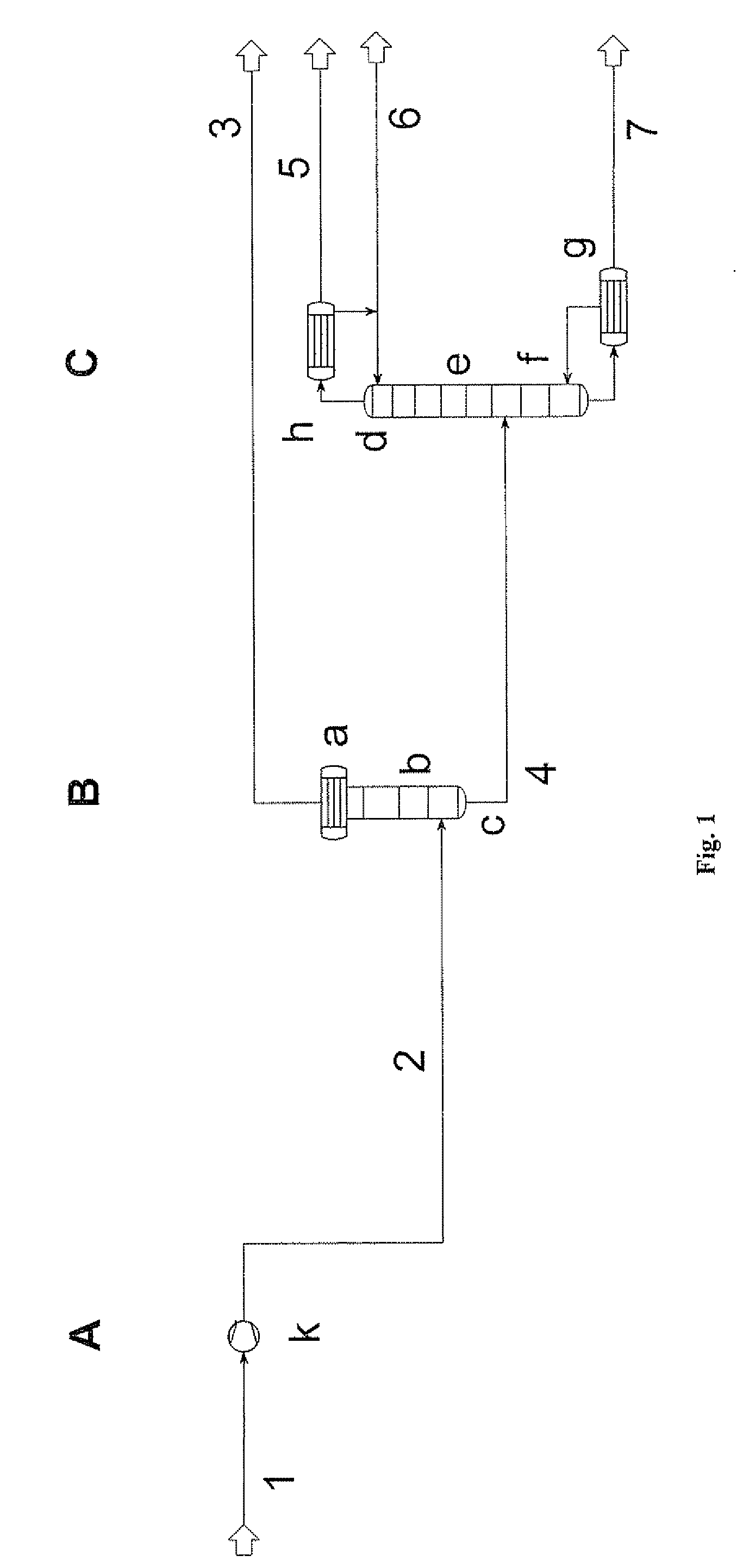
[0054]Referring to FIG. 1, the waste gas stream 1 of an upstream Deacon process (not shown), consisting of nitrogen, oxygen and carbon dioxide with a proportion of chlorine in the order of magnitude of 10 wt. %, is brought to a pressure of 35 bar (35,000 hPa) in the first stage A by means of a fan (compressor) k.

[0055]The compressed stream 2 is fed in the second stage B to a gas-liquid contact zone b in which the gas stream 2 is brought into contact with condensed chlorine. Above the gas-liquid contact zone b is a condenser a in which chlorine is condensed at a temperature of −42° C. The chlorine condensate is collected in the sump c of the gas-liquid contact zone b and fed as stream 4 to the third stage C. The uncondensed gases are discharged as stream 3 and are re-used or discarded as required, optionally after destruction of very small residual amounts of chlorine.

[0056]The condensate 4 is fed to a rectifying column d and applied in the middle region between the concentrating sec...

example 2

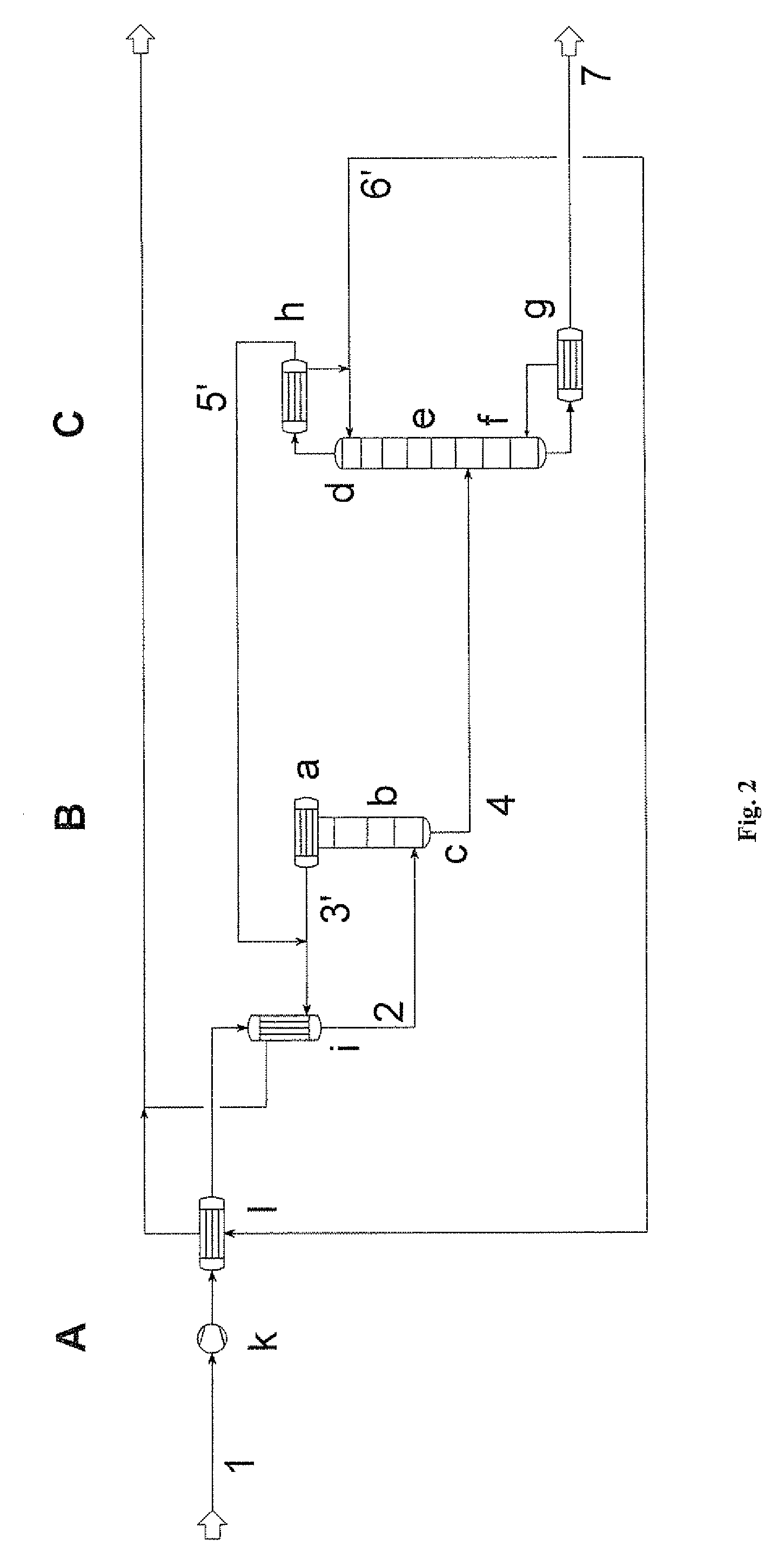
[0059]Referring to FIG. 2, the condensate stream 6′ from the rectifying column of stage C is vaporized in a first tubular heat exchanger 1 downstream of the fan k, and the waste gas stream coming from the first stage A is cooled thereby. The pre-cooled waste gas stream 2′ is passed through a recuperator (tubular heat exchanger i), in which heat is exchanged between the waste gas stream 2′ and the waste gas stream 3′ coming from the second stage B.

[0060]In addition, the gas stream 5′ leaving the third stage C is mixed with the gas stream 3′ leaving the head condenser a, and the mixture is passed through the recuperator i and then combined with the stream 6′ leaving the tubular heat exchanger 1 and discharged.

example 3

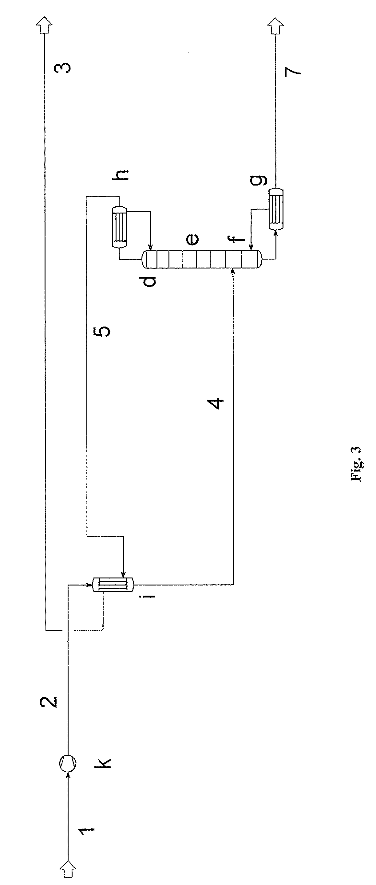
[0061]Referring to FIG. 3, heat is exchanged between the stream 2 and the stream 5 in a recuperator i downstream of the fan k. The stream 4 so obtained is fed directly to a rectifying column d. The stream 3 is discharged and re-used or discarded as required, optionally after destruction of very small residual amounts of chlorine that may remain.

[0062]In the column, the vapor stream produced in the vaporizer g is brought into contact, in a plurality of stages and countercurrently, with the vapor condensed in the head condenser h. Gas-liquid contact is effected by means of material-exchange plates (not shown).

[0063]The head condenser h is in the form of a partial condenser in order to allow inert components to be discharged in the gaseous state (stream 5). The condensate that forms is fed back to the column d. The chlorine concentrations at the column head (stream 5, FIG. 3) and at the column sump (stream 7) depend substantially on the energy supplied to the vaporizer and on the amoun...


PUM


Abstract

Processes comprising: providing a gas stream comprising chlorine and at least one secondary component selected from the group consisting of carbon dioxide, nitrogen and oxygen; pressurizing the gas stream in a first stage to an elevated or enhanced pressure, preferably at least about 10 bar; cooling the pressurized gas stream in a second stage comprising a condensation zone and a gas/liquid contact zone disposed below the condensation zone, such that at least a portion of the chlorine is condensed and contacted countercurrently in the gas/liquid contact zone with the pressurized gas stream entering the second stage to form a condensate; and separating the condensate in a third stage comprising a rectifying column to provide a chlorine-rich sump stream and a low-chlorine head stream.

Description

BACKGROUND OF THE INVENTION[0001]In a large majority of industrial chemical processes, waste gas streams containing multi-component mixtures are formed. The components of various waste gas streams can be super- or sub-critical. Furthermore, depending upon the particular jurisdiction and the scope of legislation, such waste gas components can be regarded as inert or as harmful substances.[0002]In any case, in many processes, efforts are generally made to treat waste gas streams to separate out as completely as possible the harmful substances contained in the waste gas, and to feed such harmful substances in question back into the production process in an economically advantageous manner, so that they are at the same time valuable substances.[0003]In particular, for example, in chlor-alkali electrolysis, HCl electrolysis, the Deacon process and in further chlorochemical processes, waste gas streams consisting of chlorine, carbon dioxide, nitrogen and / or oxygen, as well as farther seco...

Claims


Application Information

Patent Timeline
Patent Type & Authority Applications(United States)
IPC IPC(8): B01D53/68
CPCC01B7/0743
Inventor BRETTSCHNEIDER, OLEWERNER, KNUD
Owner BAYER MATERIALSCIENCE AG
Why Eureka
Try Eureka