

Fiducial marker
a technology of facial markers and follicles, applied in the field of facial markers, can solve the problems of difficult production of artefacts, difficulty in accurately interpreting images, and association with such materials
- Summary
- Abstract
- Description
- Claims
- Application Information
AI Technical Summary
Benefits of technology
Problems solved by technology
Method used
Image

Examples
example 1
Preparation of polyetheretherketone-Based Fiducial Markers
[0112]PEEK OPTIMA LT3 polymer and a highly pure grade of barium sulphate comprising greater than 98% of particles 10 μm or less were compounded in a twin screw melt extrusion compounder and a lace produced of 2-3 mm diameter. The lace was passed to a conveyor, cooled and then chopped into granules. The granules were then introduced into an extruder and monofilaments produced which were then chopped to produce fiducial markers of predetermined lengths comprising polyetheretherketone polymer with barium sulphate dispersed substantially homogenously throughout the polymer.
examples 2 to 16
AND C1 TO C4
[0113]Following the procedure described in Example 1, fiducial markers having different levels of barium sulphate and / or different dimensions were prepared as shown in Table 1.
TABLE 1AmountDiameterLengthAmountbariumofofExamplepolyetheretheketonesulphatemarkermarkerNo(wt %)(wt %)(mm)(mm)29461.5239461.5349461.54590101.52690101.53790101.54880201.52980201.531080201.541170301.521270301.531370301.541480200.921580200.931680200.94
[0114]The markers of examples 2 to 16 were compared to conventional metal wire markers as described in Table 2.
TABLE 2Diameter ofLength ofExample NoMetalmarker (mm)marker (mm)C1Pt0.92C2Pt0.93C3Pt0.94C4Au1.05
[0115]The markers of Examples 2 to 16, and C1 to C4 were assessed by CT-imaging. In each case it was found that the markers of Examples 2 to 16 produced very significantly fewer artefacts compared to the metal markers.
examples 17 , 18
EXAMPLES 17, 18, C5 AND C6
Comparison of polyetheretherketone-Based Markers and Metal Markers in Various Imaging Systems
[0116]Fiduciary markers described in Table 3 were assessed in various imaging systems.
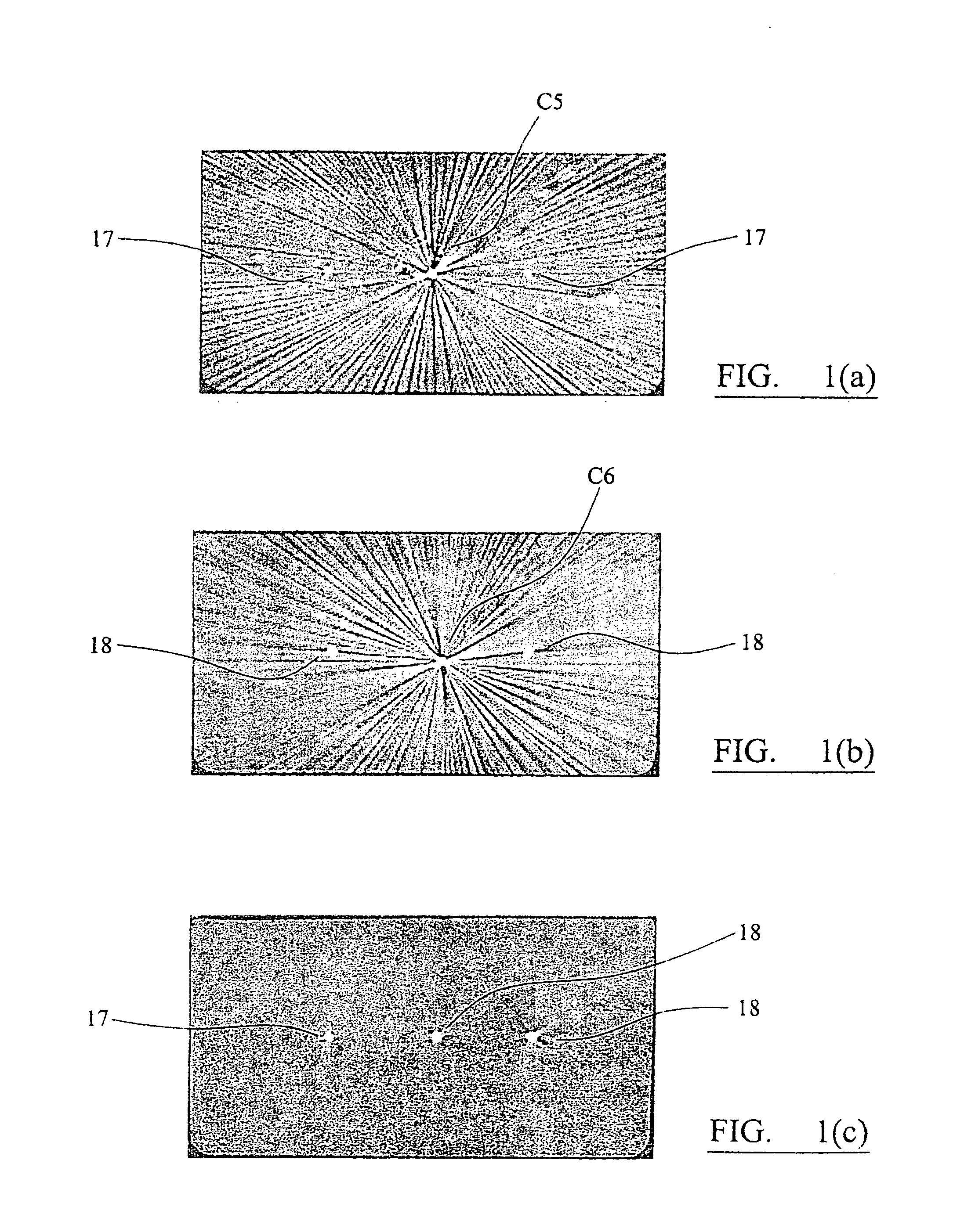
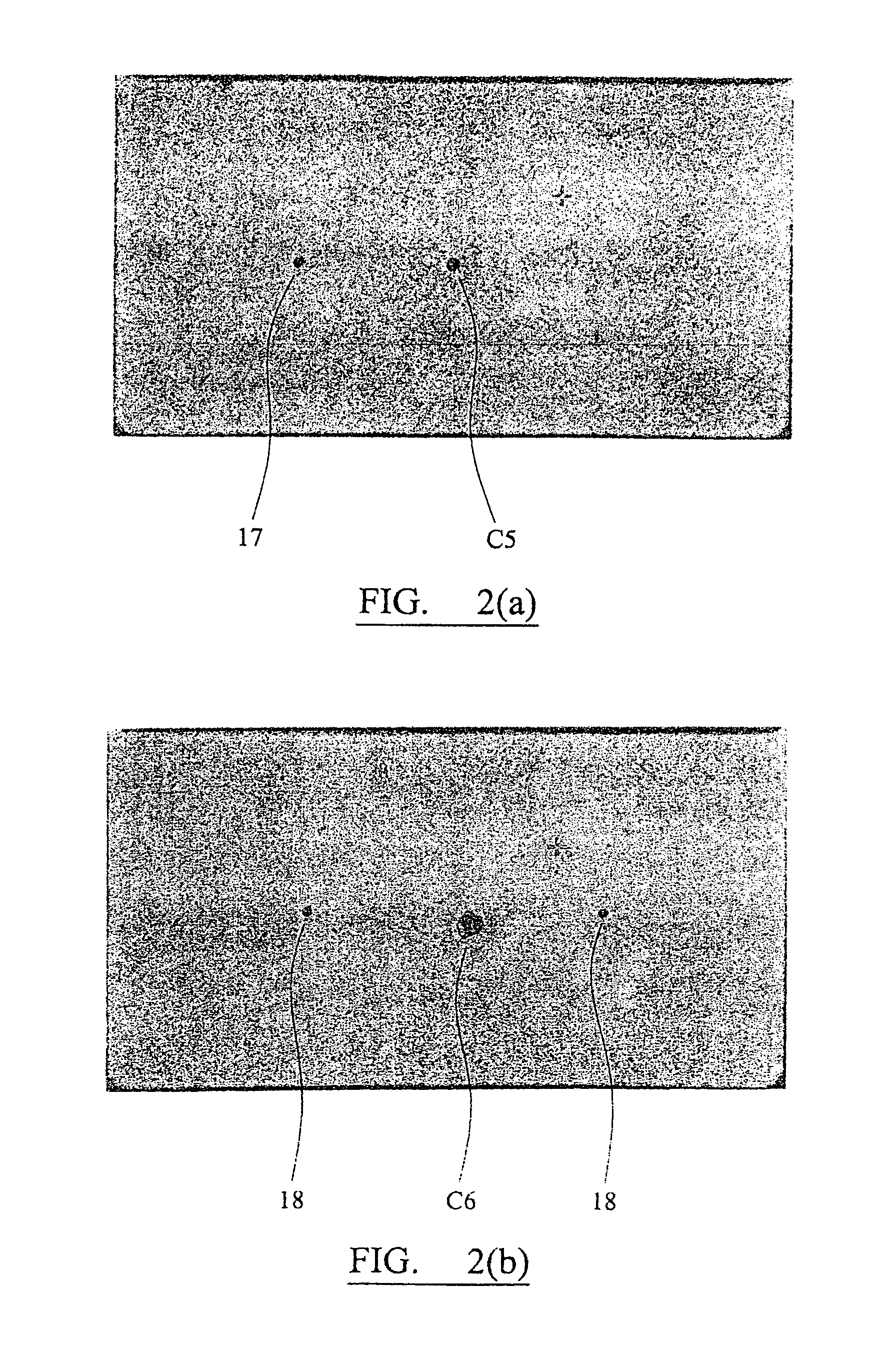
TABLE 3AmountDiameterLengthAmountbariumofofExamplepolyetheretherketonesulphatemarkermarkerNo(wt %)(wt %)Metal(mm)(mm)177030—0.94187030—1.54C5——Au0.94C6——Pt0.94
[0117]Referring to FIG. 1(a), the central spot is the CT image of Example C5 from which it will be noted that there is a significant level of distortion and a significant starburst effect, in comparison to the two Example 17 markers which are nonetheless still clearly visible.
[0118]Similarly, referring to FIG. 1(b), the Example C6 marker is substantially distorted and has produced a significant starburst effect compared to the two Example 18 markers.
[0119]FIG. 1(c) illustrates changes in the images when wider diameter markers are used (compare Examples 17 and 18 and note that each of the markers is highly visible and has sign...
PUM
 Abstract
Description
Claims
Application Information