Method and system for dynamic switching between multiplexed interfaces

Inactive Publication Date: 2008-09-25
VIA TECH INC
View PDF6 Cites 13 Cited by
  • Summary
  • Abstract
  • Description
  • Claims
  • Application Information

AI Technical Summary

Benefits of technology

[0006]Accordingly, the invention provides a bridge design and interface control method thereof for dynamically switching between different interfaces to provide simple and flexible design and reduce the pin number requirement.

Problems solved by technology

Thus, the size and pins required for the bridge will be increased, and the design of the bridge complicated.

Method used


Image

  • Method and system for dynamic switching between multiplexed interfaces
  • Method and system for dynamic switching between multiplexed interfaces
  • Method and system for dynamic switching between multiplexed interfaces

Examples


Embodiment Construction

[0016]The following description is of the best-contemplated mode of carrying out the invention. This description is made for the purpose of illustrating the general principles of the invention and should not be taken in a limiting sense. The scope of the invention is best determined by reference to the appended claims.

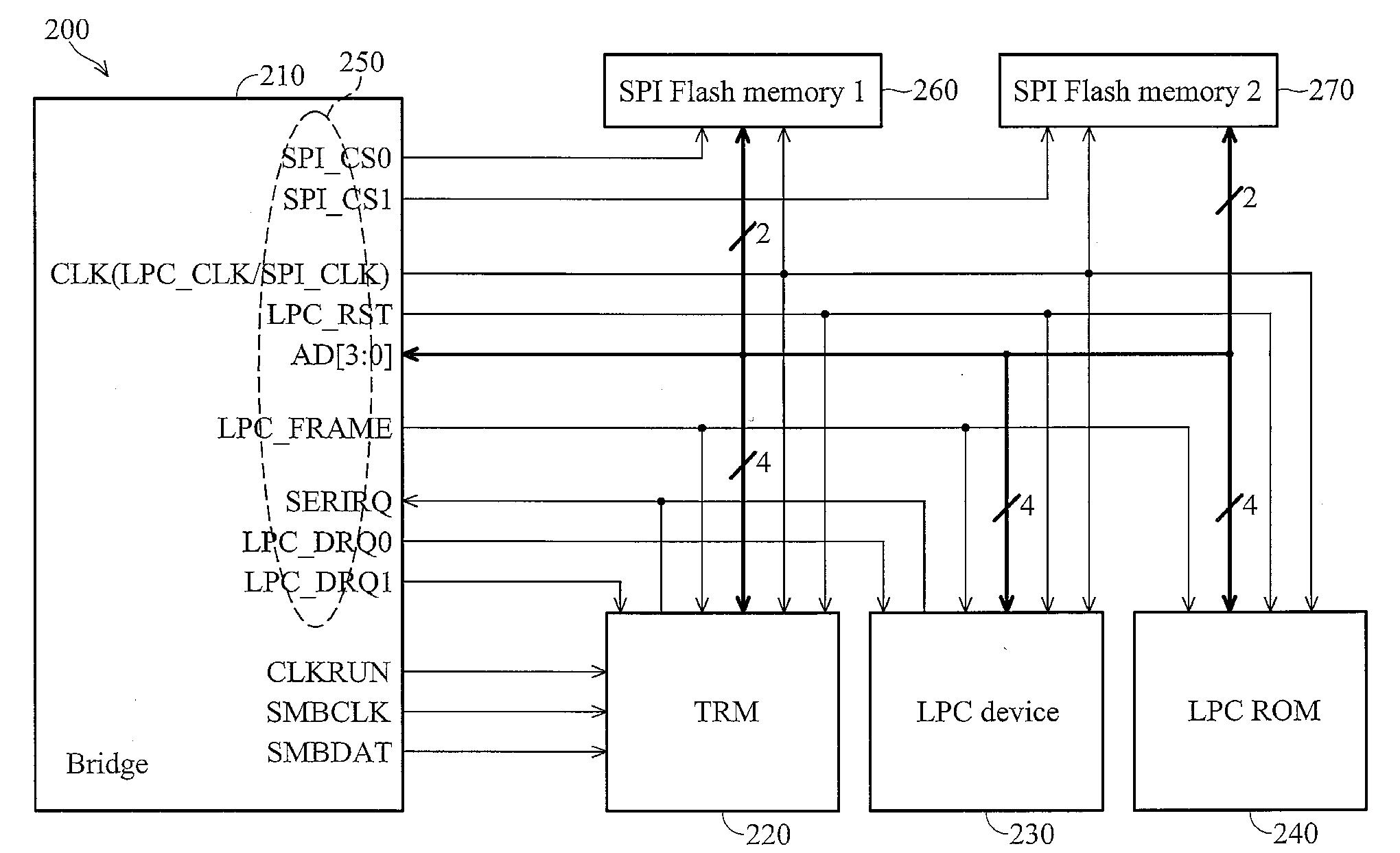
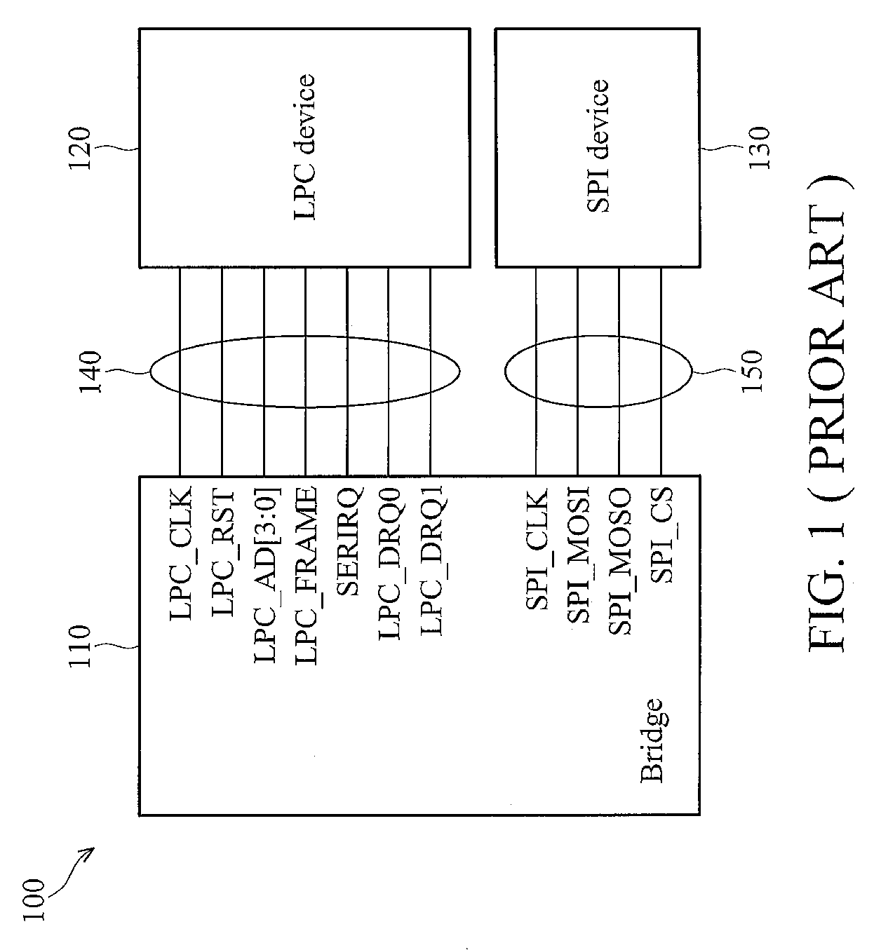
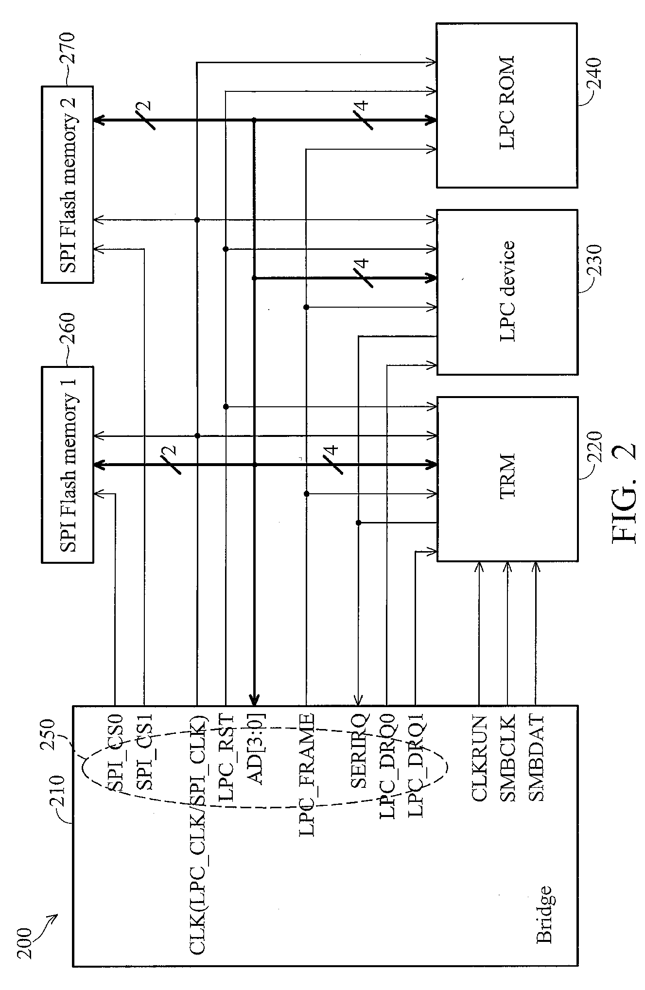
[0017]The invention relates to a bridge design, wherein the bridge comprises at least one multiplexed interface providing two interfaces with two kinds of specifications. The multiplexed interface comprises at least one multiplexed clock signal line, or multiplexed clock pins, and a first clock signal (LPC_CLK) and a second clock signal (SPI_CLK) are selectively output to the multiplexed clock signal line to access a first device (LPC device) and a second device (SPI device) in which the first and second devices are coupled to the bridge. The first device has a LPC interface and the second device has a SPI, and the first and second devices are coupled to the multiplexe...


PUM


Abstract

A bridge is disclosed. The bridge comprises a first interface having at least one multiplexed clock signal line. The multiplexed clock signal line outputs first and second control signals for respectively controlling the access to first and second devices coupled to the bridge. The bridge selectively outputs the first clock signal or the second clock signal to the multiplexed clock signal line to access the first device or the second device respectively.

Description

BACKGROUND OF THE INVENTION[0001]1. Field of the Invention[0002]The invention relates to a bridge and interface control method thereof, and more particularly, to a bridge capable of dynamically switching between different interfaces and an interface control method thereof.[0003]2. Description of the Related Art[0004]Serial peripheral interface (SPI) and low pin count (LPC) are two popular interfaces for data transmission in a conventional chipset or bridge design of electronic systems. LPC interface, or the LPC bus, is typically used in connecting devices with lower bandwidth, e.g. a bootable read only memory (ROM) or a super input / output device, to the central control unit (CPU). The LPC interface specifies seven major signals to perform bi-directional data transmission in which three of seven major signals LPC_FRAME, LPC_RST and LPC_CLK are control signals and remaining four signals LPC-AD[3:0] are data signals. LPC_FRAME signal is a frame bit signal for enabling a LPC device whic...

Claims


Application Information

Patent Timeline
IPC IPC(8): G06F13/36
CPCG06F13/405
Inventor YU, CHIA-HSINGCHEN, LIN-HUNG
Owner VIA TECH INC
Why Eureka
Try Eureka