Optical disc apparatus

a technology of optical discs and optical discs, applied in the field of optical disc apparatuses, can solve problems such as scratches on the optical disc surface, and achieve the effect of solid reliability and elimination of scratches on the disc surfa

Inactive Publication Date: 2008-09-25
HITACHI-LG DATA STORAGE
View PDF18 Cites 12 Cited by
  • Summary
  • Abstract
  • Description
  • Claims
  • Application Information

AI Technical Summary

Benefits of technology

[0009]In view of the circumstances of the related art as described above, it is desirable for the emergency eject operation in the optical disc apparatus to prevent the objective lens or the protector of the objective lens from coming into contact with the disc surface until the rotation of the optical disc is stopped or almost stopped, and to eliminate scratches on the disc surface.
[0010]The present invention aims to solve the above described problem and to provide an optical disc apparatus with solid reliability.
[0011]The present invention is a technology that can solve the above described problem and achieve the above described object.

Problems solved by technology

In such an optical disc apparatus, when an emergency eject operation is performed as a normal disc eject operation is disabled due to a power failure or other failure during recording or reproduction, a protector at the end portion of the objective lens and the disc surface come into contact with each other, for example, due to deflection of the optical disc surface during the rotation of the optical disc, causing scratches on the optical disc surface.

Method used


Image

  • Optical disc apparatus
  • Optical disc apparatus
  • Optical disc apparatus

Examples


Embodiment Construction

[0025]Hereinafter preferred embodiments of the present invention will be described with reference to accompanying drawings.

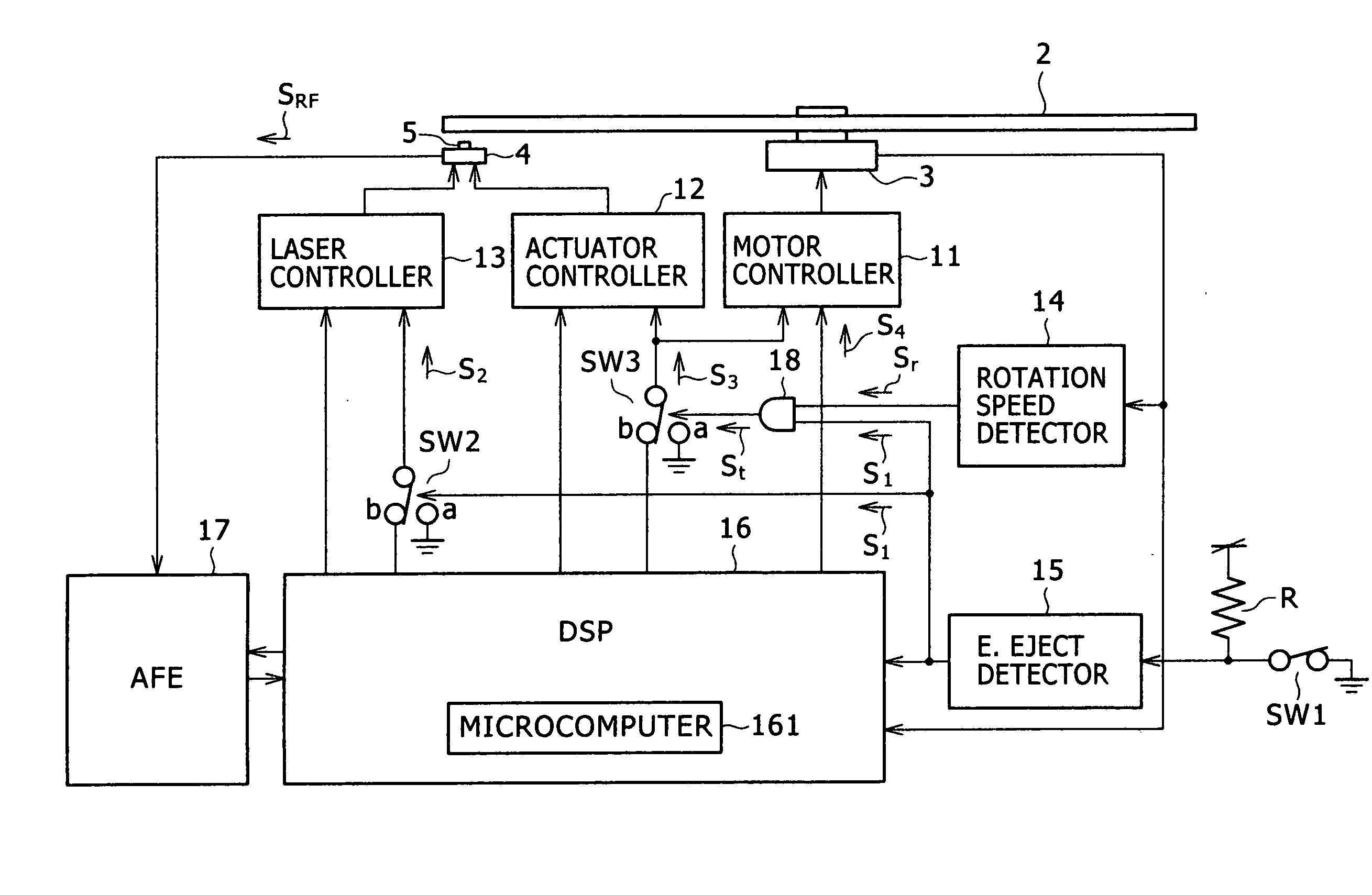
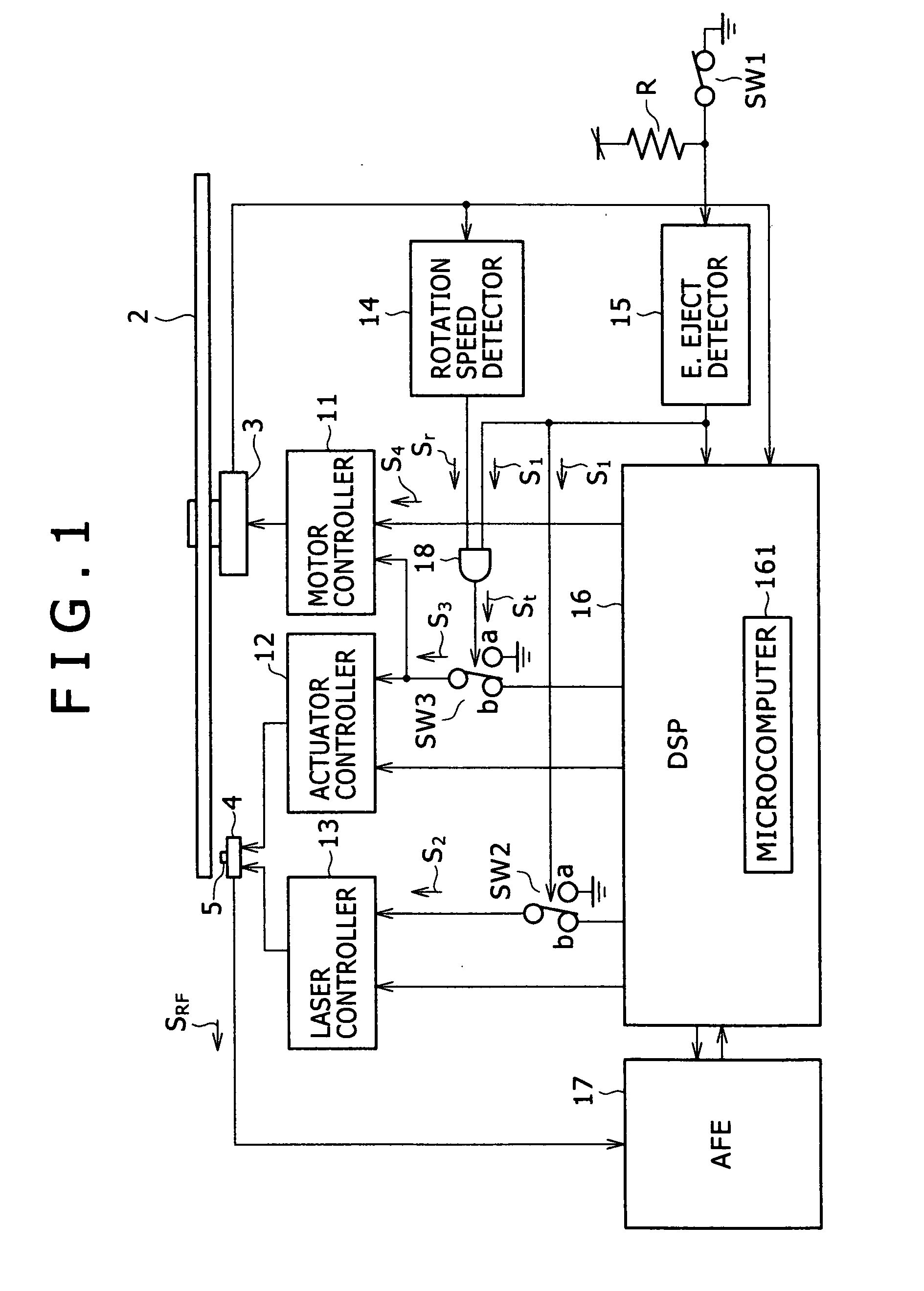
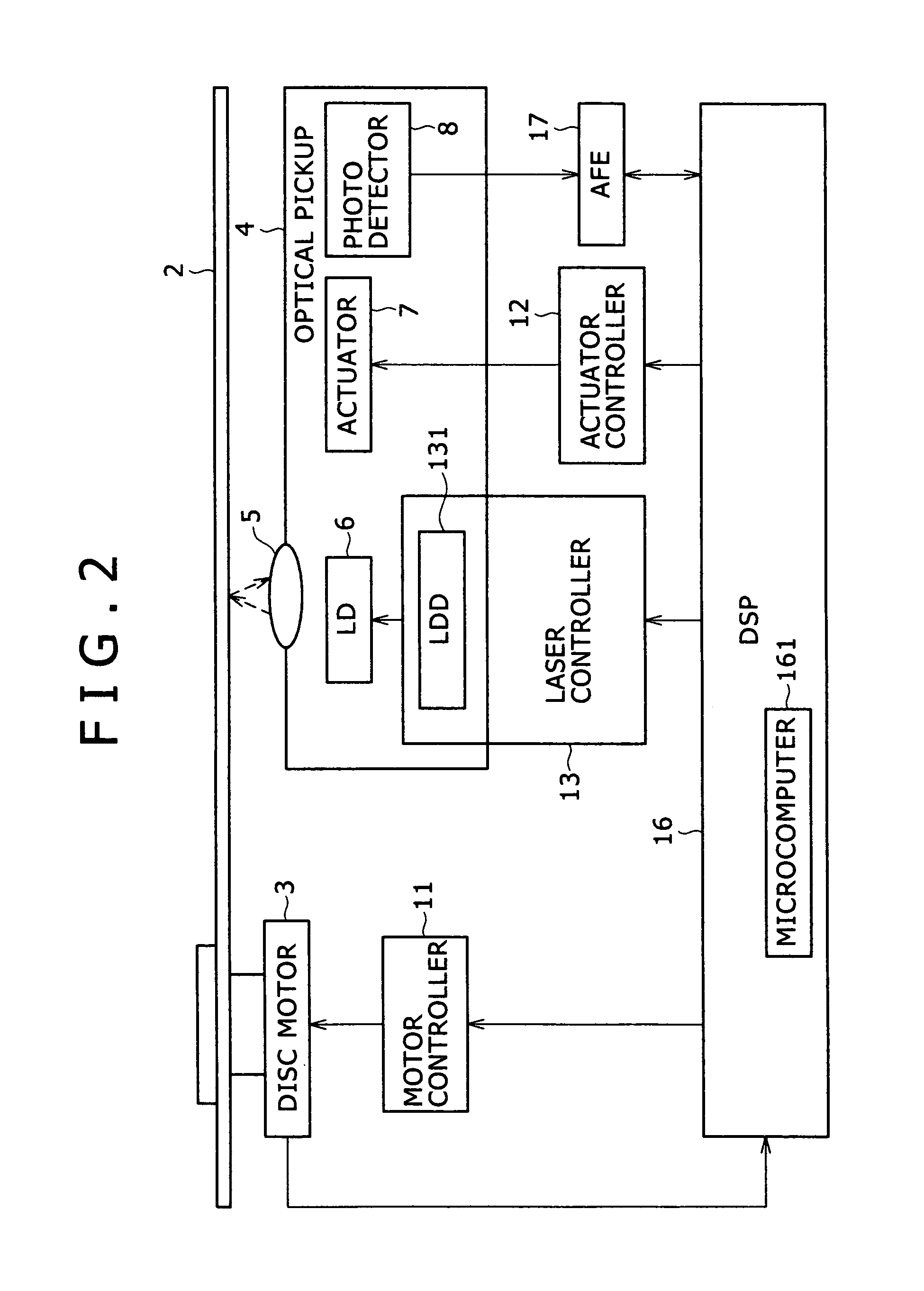
[0026]FIGS. 1 to 4 are diagrams illustrating a first embodiment of the present invention. FIG. 1 is a block diagram of an optical disc apparatus as a first embodiment of the present invention. FIG. 2 is a diagram illustrating the configuration of an optical pickup in the optical disc apparatus in FIG. 1. FIG. 3 is a diagram showing the operation states of the respective units in an emergency eject operation in the optical disc apparatus in FIG. 1. FIG. 4 is a flowchart of the emergency eject operation in the optical disc apparatus in FIG. 1. The first embodiment exemplifies the case in which, in the emergency eject operation, an objective lens is saved apart from a disc surface of the optical disc as an actuator control, and the saving state is released when the rotation speed of the optical disc is sufficiently reduced by friction of a brake pad.

[0027]In FIG. 1...


PUM

PropertyMeasurementUnit
rotation speedaaaaaaaaaa
brake forceaaaaaaaaaa
forceaaaaaaaaaa

Abstract

To eliminate scratches on a disc surface of an optical disc in an emergency eject operation, there is provided an optical disc apparatus including: an emergency eject detector for detecting an emergency eject instruction; a rotation speed detector for producing a signal corresponding to the rotation speed of the optical disc; and a logical circuit unit which is operated by a first signal from the emergency eject detector and a second signal from the rotation speed detector, and when the second output signal is not more than a reference level, produces a third signal so as to input a control signal for instructing stop of the actuator control into an actuator controller. After detection of the emergency eject instruction, the apparatus performs the actuator control without producing the third signal until the rotation speed is not more than a predetermined value. Thus the objective lens is made in a focus control state or in a saving state in which the objective lens is separated from the disc surface.

Description

CLAIM OF PRIORITY[0001]The present application claims priority from Japanese application serial No. P2007-070855, filed on Mar. 19, 2007, the content of which is hereby incorporated by reference into this application.BACKGROUND OF THE INVENTION[0002]1. Technical Field of the Invention[0003]The present invention relates to an optical disc apparatus, and more particularly a configuration for performing an emergency eject operation.[0004]2. Description of the Related Art[0005]An example of a technology related to the present invention may be found in a patent document, such as JP-A No. 182905 / 2005. In JP-A No. 182905 / 2005, there is described a technology for reducing the time until a disc is stopped rotating when the disc is ejected from a disc rotation device, by providing a brake device for braking the disc rotation by coming into contact with a rotation part of a rotation drive mechanism for rotating and driving the disc held therein, and by applying a friction force to the rotation...

Claims


Application Information

Patent Timeline
Patent Type & Authority Applications(United States)
IPC IPC(8): G11B17/03
CPCG11B17/051
Inventor WASHIYA, NOBUHIROONO, KAZUHIKO
Owner HITACHI-LG DATA STORAGE
Why Eureka
Try Eureka