Paintball loader systems

a loader system and paintball technology, applied in the direction of compressed gas guns, white arms/cold weapons, weapons, etc., can solve the problems of reducing the firing speed of paintballs, affecting the accuracy of paintballs, and controlling the force of paintballs, so as to reduce the adjacent paintball-related debris

Inactive Publication Date: 2008-10-02
BOSCH JOHN P MR
View PDF15 Cites 36 Cited by
  • Summary
  • Abstract
  • Description
  • Claims
  • Application Information

AI Technical Summary

Benefits of technology

[0007]It is a further object and feature of the present invention to provide such a system that provides high loading speeds while reducing paintball breakage during loading. It is another object and feature of the present invention to provide such a system that provides high loading forces while reducing point loads on surface of the paintballs.
[0008]It is another object and feature of the present invention to provide such a system that maintains a substantially constant loading on a paintball “stack” extending to the paintball gun. It is a further object and feature of the present invention to provide such a system that assists in removing debris from the paintball storage compartment of the loader. It is another object and feature of the present invention to provide such a system that can be disassembled for cleaning without the use of tools.
[0009]It is another object and feature of the present invention to provide such a system that utilizes a lightweight auger and that adjusts the rotation of the auger in response to the firing rate of the paintball gun. It is another object and feature of the present invention to provide such a system It utilizes a resilient auger to control force loads on the paintballs during loading. It is a further object and feature of the present invention to provide such a system that reduces transfer loads between paintballs by reducing the length of the paintball “stack”. It is another object and feature of the present invention to provide such a system that relocates stored paintballs from poor loading positions to favorable loading positions.
[0024]In accordance with another preferred embodiment hereof, this invention provides a paintball loader system comprising: at least one paintball storage compartment to store paintballs; at least one ball passage structured and arranged to pass the paintballs between such at least one paintball storage compartment and at least one paintball gun; at least one rotating conveyor to convey the paintballs from such at least one paintball storage compartment to such at least one ball passage; at least one catch tray structured and arranged to catch ball-associated debris occurring within such at least one paintball storage compartment during use; and at least one debris passage structured and arranged to pass such ball-associated debris from such at least one paintball storage compartment to such at least one catch tray, and restrict passage of the paintballs from such at least one paintball storage compartment to such at least one catch tray; wherein operation of such at least one rotating conveyor moves the paintballs generally toward such at least one ball passage and assists movement of such ball-related debris to such at least one catch tray; and wherein a reduction of paintball-related debris adjacent the paintballs during delivery to the at least one paintball gun is achieved.

Problems solved by technology

Electronically controlled guns are generally capable of very high rates of fire, so much so that the limiting factor in firing speed is typically the rate at which “paint” can be loaded into the gun.
Often a player will experience missed shots or skipped shots due to a hopper not keeping up with the operation of the gun.
A significant problem with high-speed loading of paintballs is the controlled application of forces on the paintball.
High loading velocities are generally associated with the application of high levels of force to the paintballs.
The inherent fragility of the paintballs limits the maximum level of force that can be concentrated on the surface of the ball without breakage.
An additional problem related to high-speed loading of paintballs is the need for consistent feeding of paintballs into the gun, without interference or interruption.
Occasionally, a paintball will break within the hopper hindering the operation.
The closed construction of conventional hoppers makes cleaning both difficult and time-consuming.

Method used


Image

  • Paintball loader systems
  • Paintball loader systems
  • Paintball loader systems

Examples


Embodiment Construction

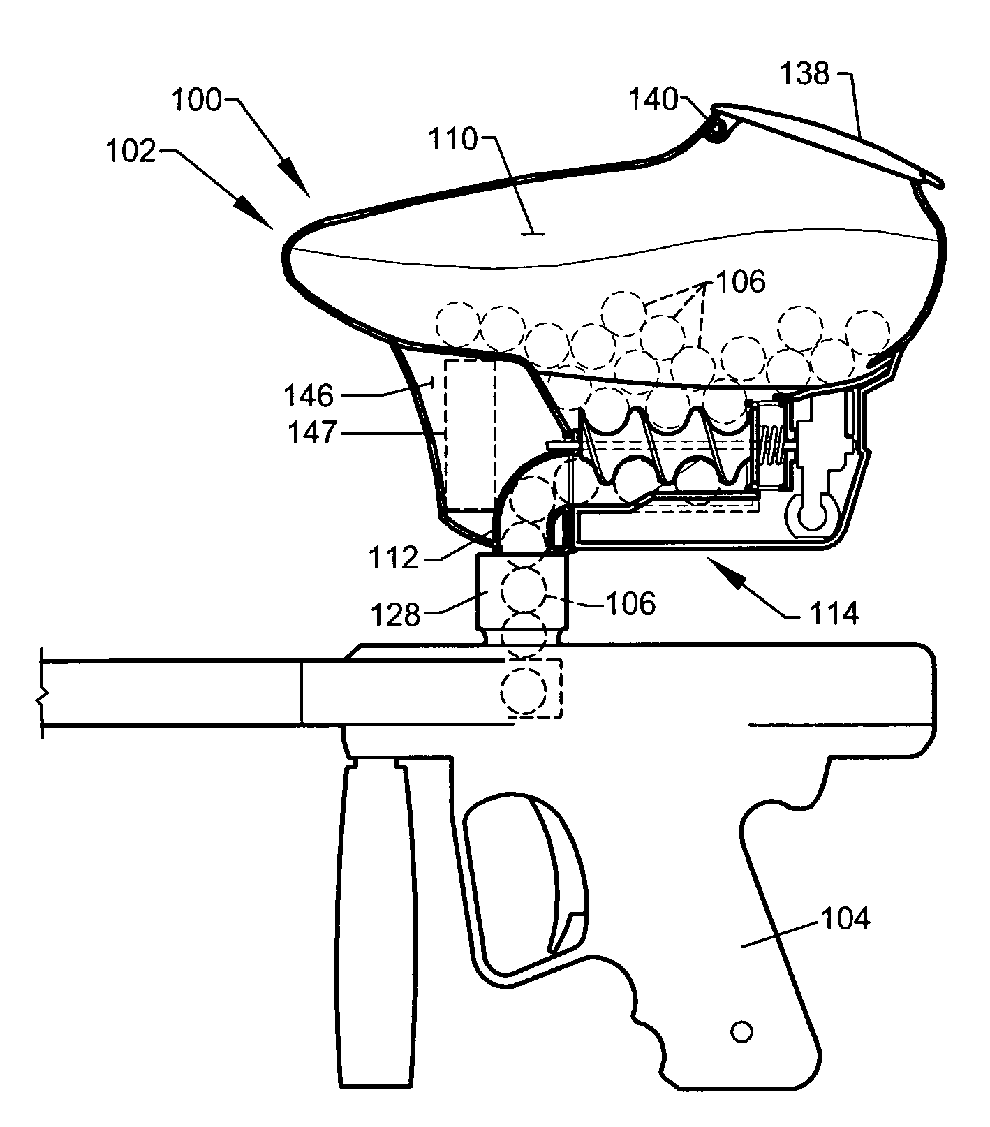
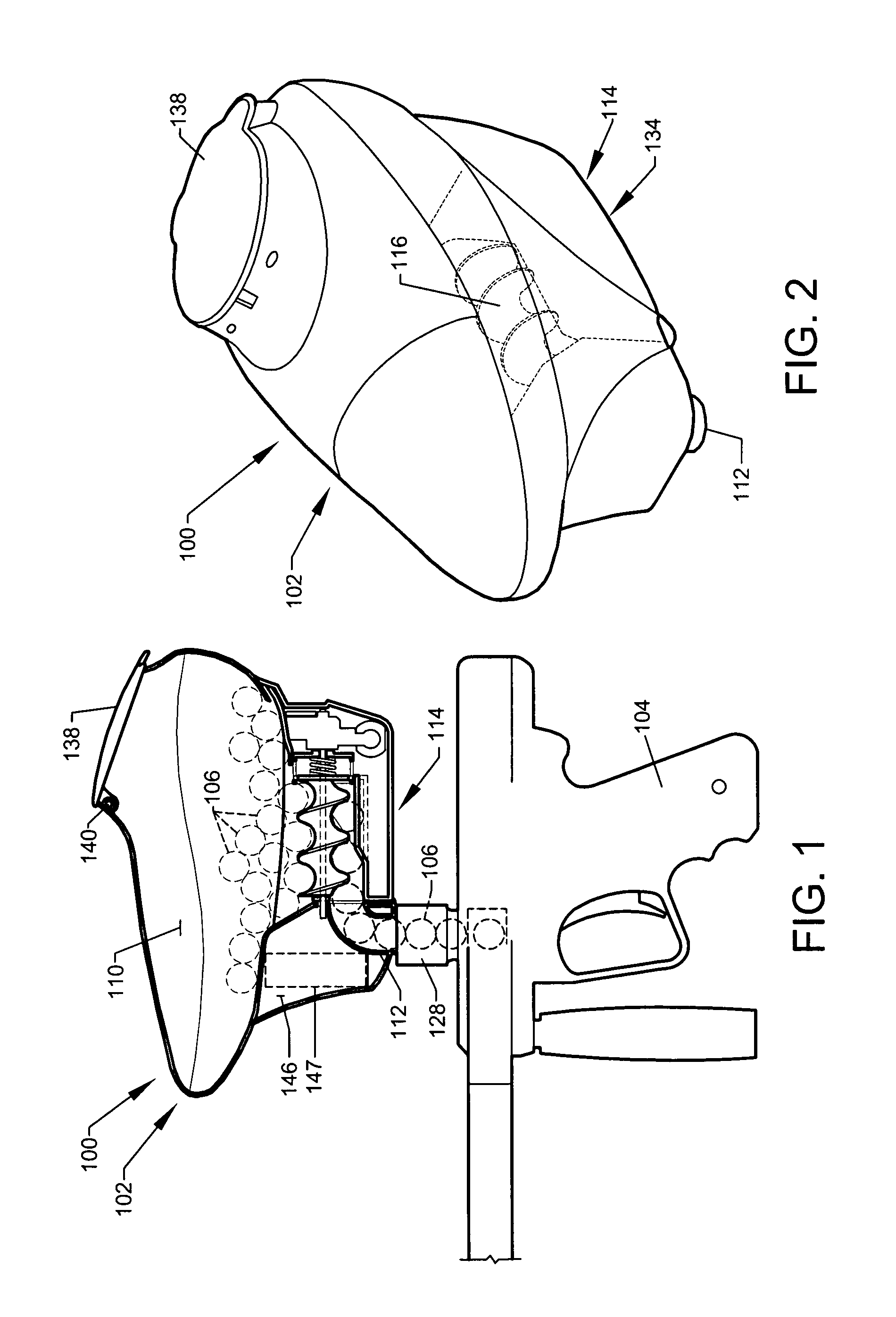
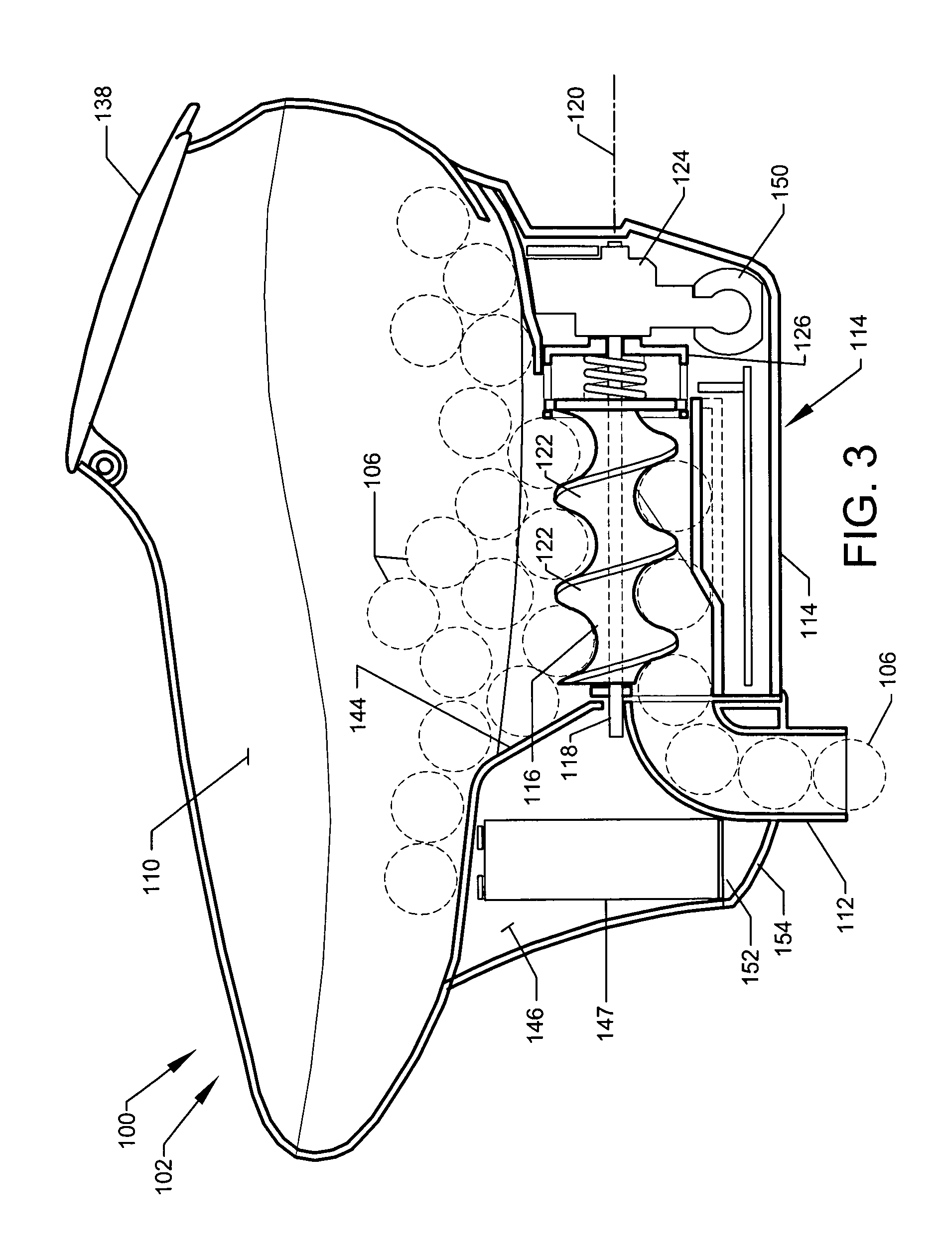
[0070]FIG. 1 shows a partial sectional view cut longitudinally through a high-speed paintball loader 102 according to a preferred embodiment of the present invention. FIG. 1 shows paintball loader 102 mounted to paintball gun 104 in a preferred operational position. FIG. 2 shows an overall perspective view of paintball loader 102 according to the preferred embodiment of FIG. 1. FIG. 3 a partial sectional view cut longitudinally through paintball loader 102 of FIG. 1.

[0071]Paintball loader 102 is illustrative of a preferred embodiment of loader system 100. Paintball loader 102 is preferably designed to hold a plurality of paintballs and to efficiently deliver the paintballs to the breach of a paintball gun at a high sustainable feed rate.

[0072]Preferably, paintball loader 102 of paintball loader system 100 comprises paintball storage compartment 110 functioning to store the plurality of paintballs 106 prior to transfer to the breach 108 of paintball gun 104, as shown. Preferably, fee...


PUM


Abstract

A paintball loader system designed to efficiently deliver paintballs to a paintball gun. The drive mechanism is a screw-type design comprising a resilient auger. A microcontroller is programmed to automatically adjust the rotation of the auger based on data from multiple sensor points within the loader. The auger is mounted such that both rotational axial movements are enabled during operation. The axial movement of the auger is used to maintain a constant force on the paintballs awaiting loading within the paintball gun.

Description

CROSS-REFERENCE TO RELATED APPLICATION[0001]The present application is related to and claims priority from prior provisional application Ser. No. 60 / 909,373, filed Mar. 30, 2007, entitled “PAINTBALL LOADER SYSTEMS”, and is related to and claims priority from prior provisional application Ser. No. 60 / 989,720, filed Nov. 21, 2007, entitled “PAINTBALL LOADER SYSTEMS”, the contents of both of which are incorporated herein by this reference and are not admitted to be prior art with respect to the present invention by the mention in this cross-reference section.BACKGROUND[0002]This invention relates to paintball loader systems. More particularly, it relates to providing paintball loader systems to efficiently deliver paintballs to a paintball gun (also known as paintball markers).[0003]The game of paintball involves participants utilizing paintball guns that discharge frangible paint-filled balls “fired” from the gun that burst upon impact to leave a mark at the point of impact. Paintball...

Claims


Application Information

Patent Timeline
Patent Type & Authority Applications(United States)
IPC IPC(8): F41B11/02
CPCF41B11/53F41B11/57
Inventor BOSCH, JOHN P.MCKAY, CLYDE
Owner BOSCH JOHN P MR
Why Eureka
Try Eureka