Quick change check valve system

a check valve and quick change technology, applied in the field of check valves, can solve the problems of requiring metal components that may corrode, drawbacks of bar arrangements, etc., and achieve the effect of quick removal and installation of check valves and reduced replacement costs

Active Publication Date: 2008-10-02
PULSAFEEDER
View PDF7 Cites 11 Cited by
  • Summary
  • Abstract
  • Description
  • Claims
  • Application Information

AI Technical Summary

Benefits of technology

[0005]The present invention meets the above described need by providing a way to quickly remove and install check valve parts without disturbing system piping attached to the pump. Replacement costs are also reduced by replacing

Problems solved by technology

The tie-bar arrangements have some drawbacks such as leakage due to misalignment or due to variations in the tightening of the

Method used


Image

  • Quick change check valve system
  • Quick change check valve system
  • Quick change check valve system

Examples


Embodiment Construction

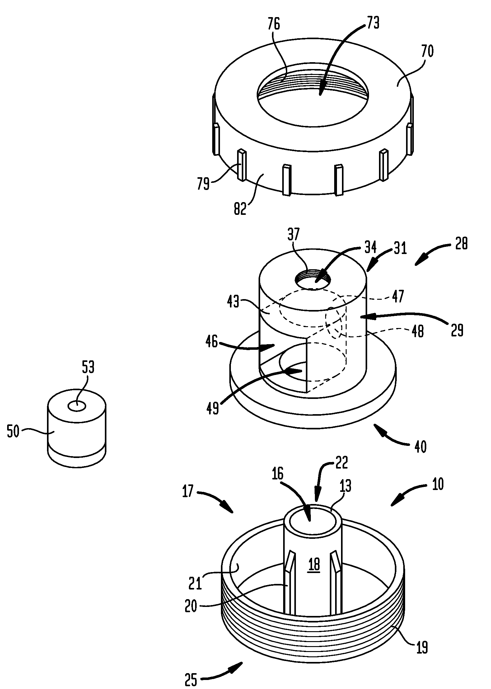
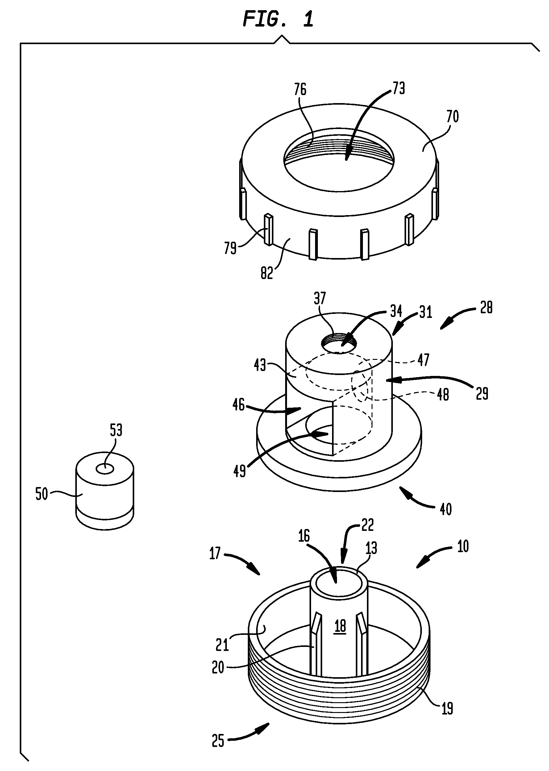
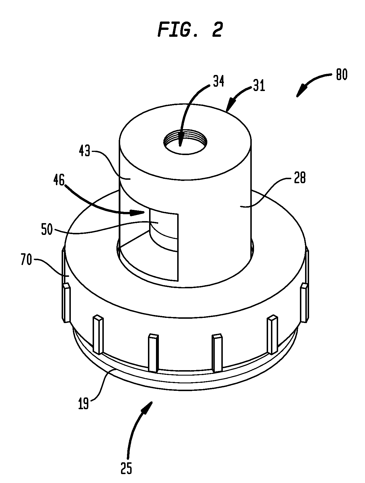
[0009]In FIG. 1, a first adapter 10 has a valve support 13 surrounding a central opening 16. The valve support 13 is disposed centrally on a upstanding member 18 with gussets 20. The upstanding member 18 is centered with respect to a housing 17. The housing 17 has a side wall 21 with a set of external threads 19 disposed thereon. The valve support 13 is disposed at a first end 22 of adapter 10. A second end 25 of adapter 10 is attached to the pump reagent head.

[0010]A second adapter 28 has a body 29 with a first end 31 having an opening 34 with a set of internal threads 37 disposed thereon. The first end 31 mates with customer supplied piping. The adapter 28 has a second end 40 that fits over the first end 22 of the first adapter 10. The body 29 has a side wail 43 with an opening 46 defined therein. The body 29 also has an opening 49 capable of being disposed in registry with opening 16 when the parts are assembled as shown in FIG. 2. The opening 49 has female slots that engage guss...


PUM


Abstract

A system for quickly removing and installing check valve parts without disturbing system piping attached to a pump. The system includes a first adapter attached to the outlet of the pump head. The first adapter includes a valve seat and a housing with a side wall having external threads. A second adapter includes a hollow body with a space for a check valve. The body has an opening in the side wall for inserting the check valve. The second adapter fits over the first adapter and the adapters are attached by means of a collar. Tightening the collar onto the threads on the first adapter causes the check valve to be held firmly between the valve seat and the top wall of the second adapter.

Description

CROSS-REFERENCE TO RELATED APPLICATION[0001]This application claims priority to U.S. Provisional Patent Application No. 60 / 920,725 filed on Mar. 29, 2007 and entitled “Quick Change Check Valve System,” which is hereby incorporated by reference.FIELD OF THE INVENTION[0002]The present invention relates to check valves for reciprocating type fluid pumps.BACKGROUND OF THE INVENTION[0003]Reciprocating type fluid pumps typically use check valves built into the pump as part of the mechanism to produce flow. As normal wearing parts of the pump, these check valves require cleaning or replacement on a regular basis. Existing methods of installing cartridge-type check valves require disassembly or extensive movement of system piping in order to remove the check valves for maintenance. One exception to this requirement is a tie-bar type, check valve clamping mechanism. The tie-bar arrangements have some drawbacks such as leakage due to misalignment or due to variations in the tightening of the ...

Claims


Application Information

Patent Timeline
IPC IPC(8): F16K43/00F16K15/00
CPCF16K15/00F16K27/0209Y10T137/6011Y10T137/7927Y10T137/0497Y10T137/6188Y10T137/0491
Inventor CLAUDE, CORDELL E.
Owner PULSAFEEDER
Why Eureka
Try Eureka