

Plasma processing apparatus
- Summary
- Abstract
- Description
- Claims
- Application Information
AI Technical Summary
Benefits of technology
Problems solved by technology
Method used
Image

Examples
Embodiment Construction
[0036]Hereinafter, embodiments of the present invention will be described with reference to FIGS. 1 to 15 which form a part hereof.
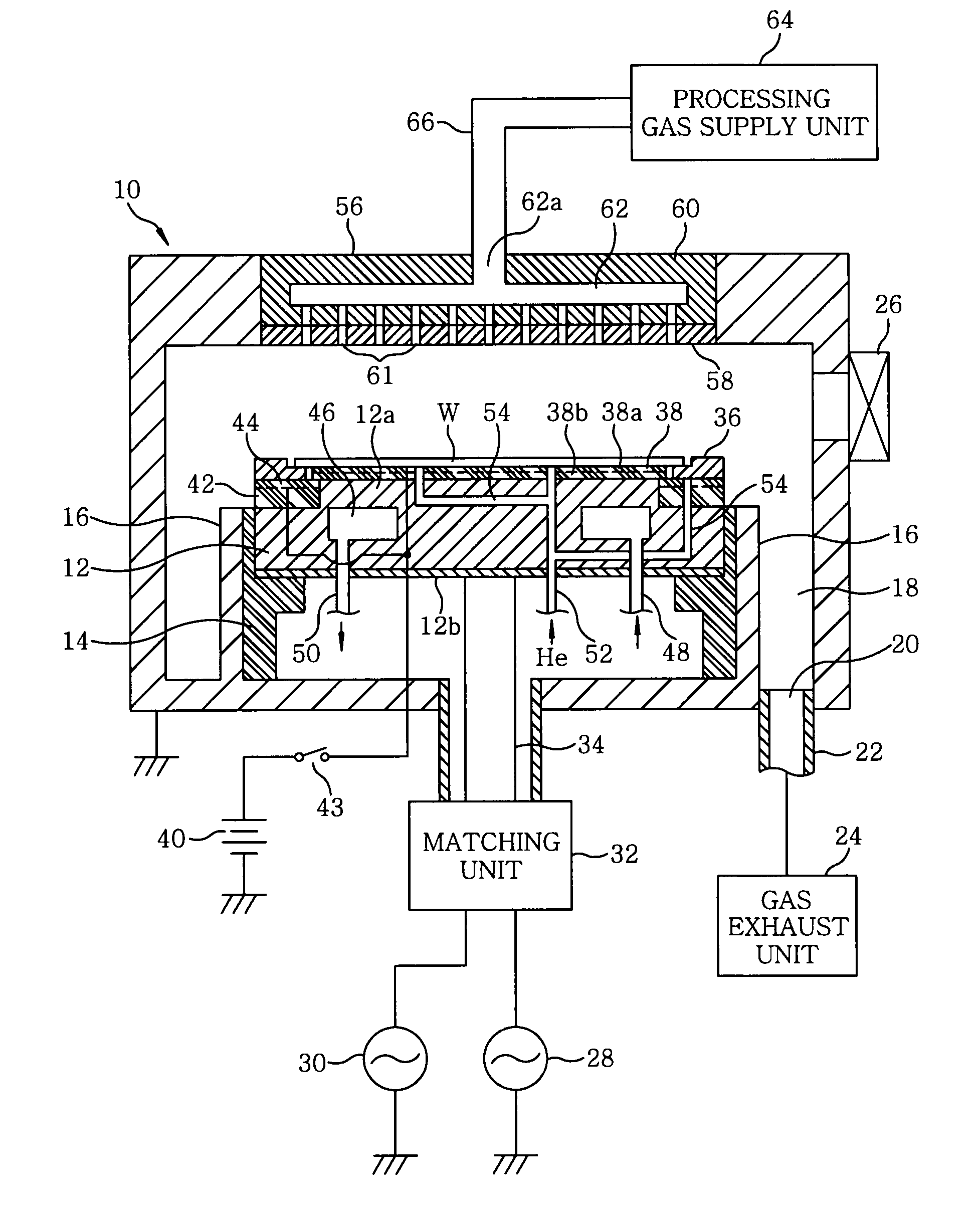
[0037]FIG. 1 is a vertical cross sectional view showing a configuration of a plasma etching apparatus in accordance with an embodiment of the present invention. This plasma etching apparatus is constructed as a capacitively coupled cathode couple plasma etching apparatus, and includes a cylindrical chamber (processing chamber) 10 made of a metal such as aluminum, stainless steel or the like. The chamber 10 is frame grounded.
[0038]A circular plate-shaped susceptor 12 serving as a lower electrode for mounting thereon a target substrate, e.g., a semiconductor wafer W, is horizontally arranged in the chamber 10. The susceptor 12 has a main body or a base 12a made of, e.g., aluminum, and a conductive RF plate 12b fixed to a bottom surface of the base 12a. Further, the susceptor 12 is supported by a cylindrical insulating supporting portion 14 extending vertic...
PUM
| Property | Measurement | Unit |
|---|---|---|
| Thickness | aaaaa | aaaaa |
| Force | aaaaa | aaaaa |
| Volume | aaaaa | aaaaa |
Abstract
Description
Claims
Application Information