Locking Apparatus

a technology of locking device and locking mechanism, which is applied in the direction of mechanical apparatus, spring/damper, shock absorber, etc., can solve the problems of inability to deactivate the effective connection between the actuating element and the catch element, high manufacturing tolerance, and extremely limited available space, so as to reduce the operating force of the locking device and improve the sticking prevention effect of the devi

Active Publication Date: 2008-10-02
ZF FRIEDRICHSHAFEN AG
View PDF15 Cites 17 Cited by
  • Summary
  • Abstract
  • Description
  • Claims
  • Application Information

AI Technical Summary

Benefits of technology

[0031]In order to keep the force that is required to deactivate the catch device to a minimum as well as to counteract sticking of the locking apparatus in the region between the spring arm and the release element, the spring arm is designed with a guide region in the area facing the release element, over which the spring arm is guided during axial displacement of the release element against the pre-tensioning of the spring arm and is thereby pivoted from a position equivalent to the closed condition of the locking apparatus, to a position equivalent to the open condition of the locking apparatus.
[0032]To further reduce the operating force of the catch device, as well as to improve sticking prevention of the device in the area, between the spring arm and the piston unit, in a further development of the subject-matter of the invention, the release element is designed with a guide surface which is positioned at the side facing the spring arm, over which the spring arm is guided during axial displacement of the release element against the tension of the spring arm and is thereby pivoted from a position equivalent to the closed condition of the locking apparatus to a position equivalent to the open condition of the locking apparatus.

Problems solved by technology

The design of the actuating element as a sprayed-on or clipped-on plastic component has the disadvantage that it requires an actuating element with thick walls and requires a large overlap region in the effective range, between the catch element and the actuating element, in order to provide the necessary holding forces, which are generally high for parking brake devices.
This is undesirable, however, since particularly in vehicle transmissions the available space is extremely limited.
Furthermore, the design of the actuating element as a punched component that is fastened to the yoke with a tension spring has the disadvantage that, in order to assure the functioning of the locking apparatus, high demands are placed on the manufacturing tolerances.
This component elasticity, however, leads to undesirable deformation of the actuating element in the engagement area of the bolt such that de-activation of the effective connection, between the actuating element and the catch element, is not possible.
This poses a disadvantage that, in their locked condition, the catch elements and the piston rod rest against one another in such a manner that the holding force, which is in effect during locking, creates a bending moment within the catch elements, which can only be counteracted by a corresponding bending stiffness of the catch elements so that the catch elements must be dimensioned accordingly.
This has the disadvantage of high manufacturing costs, a high component weight and large installation space.
The disadvantage here as well is that, in a locked condition, a bending force is transferred into the locking elements, which can only be counteracted by dimensioning the locking elements to an extent that assures the functioning of the locking apparatus.
The above described embodiments of the locking elements and the piston, when the piston is in locked condition, will allow a bending force to be applied to the locking elements which deforms the locking elements, between the bearing point and the protrusions, potentially to an extent that significantly degrades the functioning of the locking apparatus if the locking apparatus lacks a certain bending stiffness.
Such a bending stiffness can only be achieved with a locking apparatus that exhibit large component dimensions and are, therefore, distinguished by a large installation space.

Method used


Image

  • Locking Apparatus
  • Locking Apparatus
  • Locking Apparatus

Examples


second embodiment

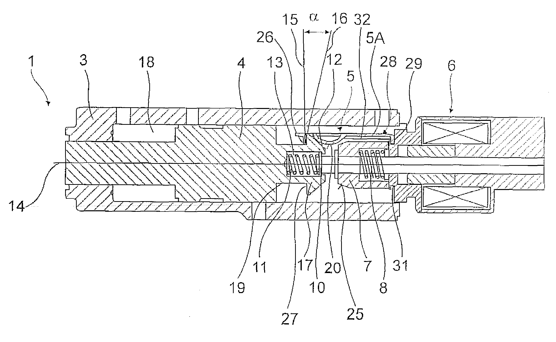
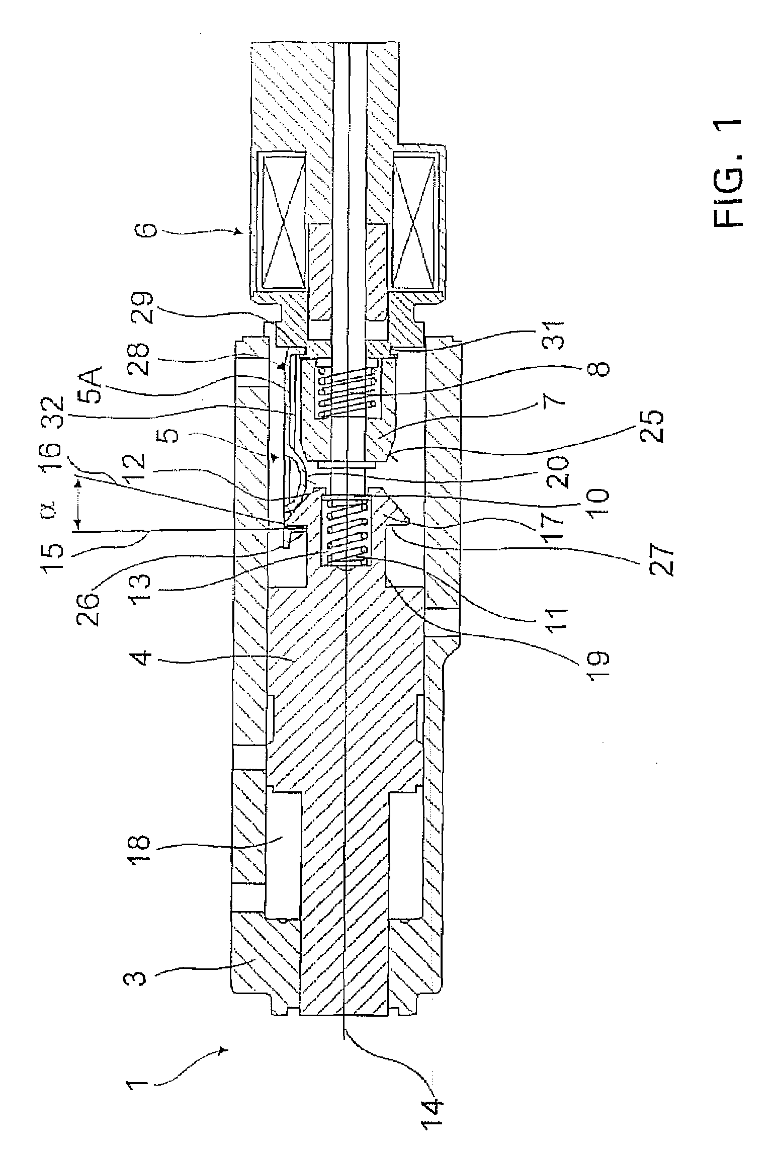
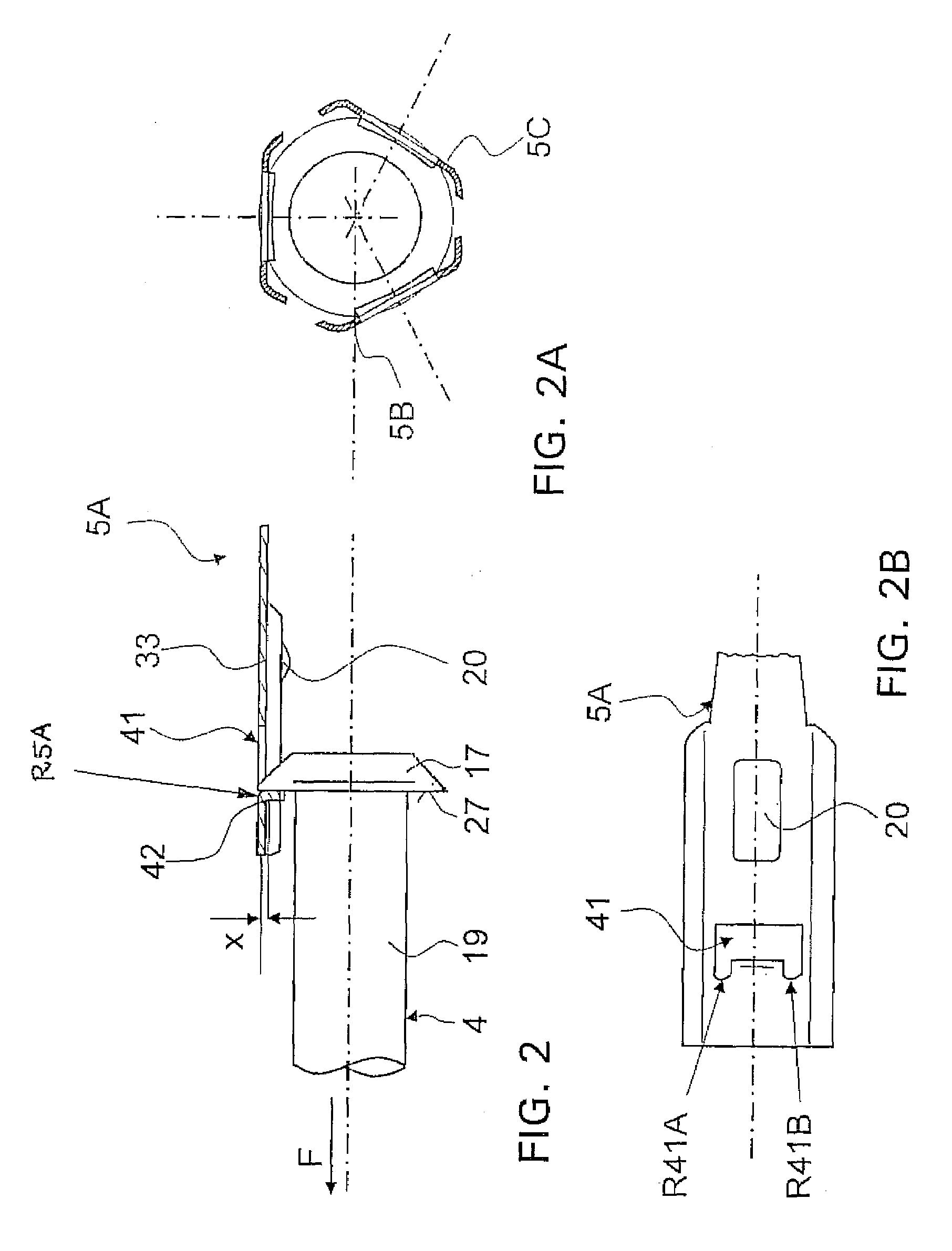
[0083]FIGS. 3A and 3B show the locking apparatus 1, according to the invention according to FIG. 1.

[0084]In addition to the recess 41, the spring arms 5A and / or 5B and 5C also have bends 32 in the longitudinal support area 33 in order to increase the bending stiffness of the spring arm 5A and / or the spring arms 5B and 5C in a longitudinal direction, while the bends 32 can be optionally shaped with a right angle or rounded in order to provide the smoothest possible transition to the longitudinal support area 33.

[0085]Additionally, the present design provides that the contact surface 26 in relation to the catch area 27, which is basically disposed vertically to the longitudinal axis of the piston unit 4, can be designed with a locking angle α, which can be provided within a range of 0° to 5°. The self-locking angle α permits simple adjustment of the locking force, which opposes the release of the locking apparatus 1 depending on the particular application. In the process, for a self-l...


PUM


Abstract

A locking apparatus, particularly of a parking brake device for a vehicle with an automatic transmission, which has a piston unit positioned inside a housing and is axially displaced and locked in a pre-defined axial position, and a catch device that automatically activates when the piston unit is locked to hold the piston unit. The catch device has at least one spring arm actively connected with the piston unit when the piston unit is locked, the spring arm abuts the piston unit in locked position with a catch area. The spring arm has a recess in a longitudinal plane of the spring arm. The piston unit penetrates the recess of the spring arm at least approximately in a radial direction with a section that forms the catch area, so that when the piston unit is locked, the catch area within the longitudinal plane of the spring arm.

Description

[0001]This application is a national stage completion of PCT / EP2006010876 filed Nov. 14, 2006, which claims priority from German Application Serial No. 10 2005 060 583.4 filed Dec. 17, 2005.FIELD OF THE INVENTION[0002]The invention relates to a locking apparatus, particularly a parking brake device for a vehicle whose drivetrain is equipped with an automatic transmission.BACKGROUND OF THE INVENTION[0003]DE 103 47 667 A1 and EP 1 408 260 A1 establish a locking device for locking the movement of a piston. The electromagnet anchor and / or its armature rod engage an actuating element which, in turn, interacts with a catch element in such a manner that the catch element in a locked position blocks the movement of the piston and / or the catch element in an unlocked position releases the movement of the piston.[0004]The actuating element is specifically pre-ensioned, the tension acting in a radial direction toward the piston rod. The actuating element is furthermore either designed as a plas...

Claims


Application Information

Patent Timeline
Patent Type & Authority Applications(United States)
IPC IPC(8): F16F9/32F16D65/28
CPCF15B15/261F16H63/3433F16H63/3475F16H63/3483F16D2127/06
Inventor MAYR, KARLHEINZ
Owner ZF FRIEDRICHSHAFEN AG
Why Eureka
Try Eureka