Induction machine

a technology of induction machine and sheared portion, which is applied in the direction of magnetic circuit rotating parts, magnetic circuit shape/form/construction, windings, etc., can solve the problems of large interior area of hysteresis curve, deformation of crystal structure of sheared portion of magnetic steel sheet, and increase of iron loss, so as to reduce iron loss and high efficiency

Inactive Publication Date: 2008-10-02
HITACHI LTD
View PDF7 Cites 27 Cited by
  • Summary
  • Abstract
  • Description
  • Claims
  • Application Information

AI Technical Summary

Benefits of technology

[0006]An object of the present invention is to provide an induction machine appropriate to reduce iron loss and realize high efficiency.

Problems solved by technology

When punching, problems occur that the crystal structure of the sheared portion of the magnetic steel sheets deforms and deteriorates their magnetic property.
The interior area of the hysteresis curve becomes large and the iron loss increases considerably.
Additionally, thick magnetic steel sheets have a disadvantage that makes eddy current loss large.
Therefore, there is a problem not to improve the efficiency of the induction machine.
Also, while a gap between the stator core and rotor core is necessary to be small as well as high precision, the insufficient precision of the punching is not able to decrease the high harmonic iron loss.

Method used


Image

  • Induction machine
  • Induction machine
  • Induction machine

Examples


embodiment 1

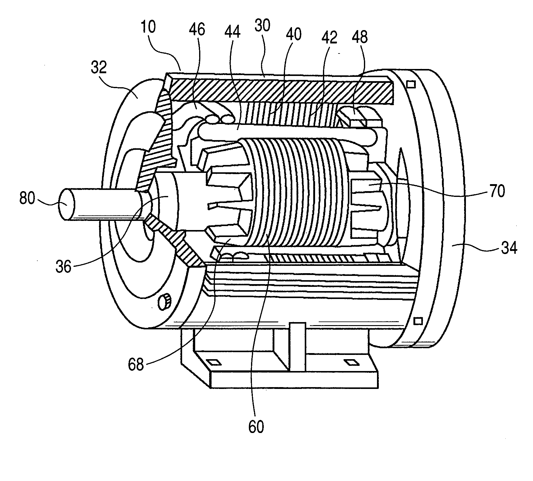
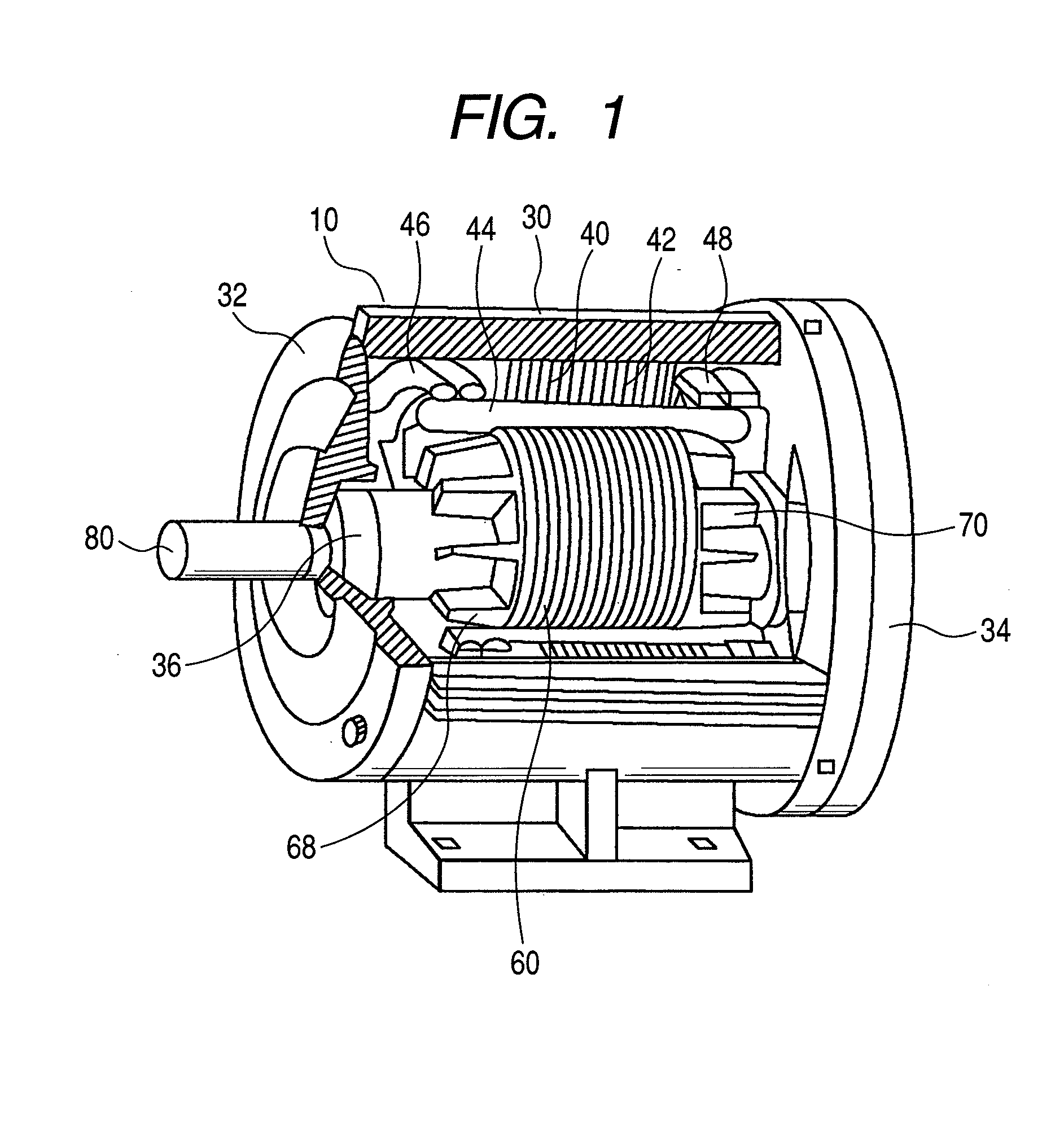
[0018]FIG. 1 shows a structure of a three-phase induction motor using magnetic steel sheets. The induction motor 10 comprises a housing 30, an end bracket 32, a fan cover 34 including a fan in the inside, a stator 40 fixed on the inside of the housing 30, a rotor 60 installed into a stator 40 and a shaft 80 supporting the rotor 60. The shaft 80 is held rotatably to both sides of the end bracket 32 by a bearing 36.

[0019]Also, a fan covered by the fan cover 34 is attached to the shaft 80 and the fan rotates according to the rotation of the shaft 80. The end bracket 32 of the fan, the bearing 36 and the fan are positioned on the inside of the fan cover 34 and these are not shown in FIG. 1.

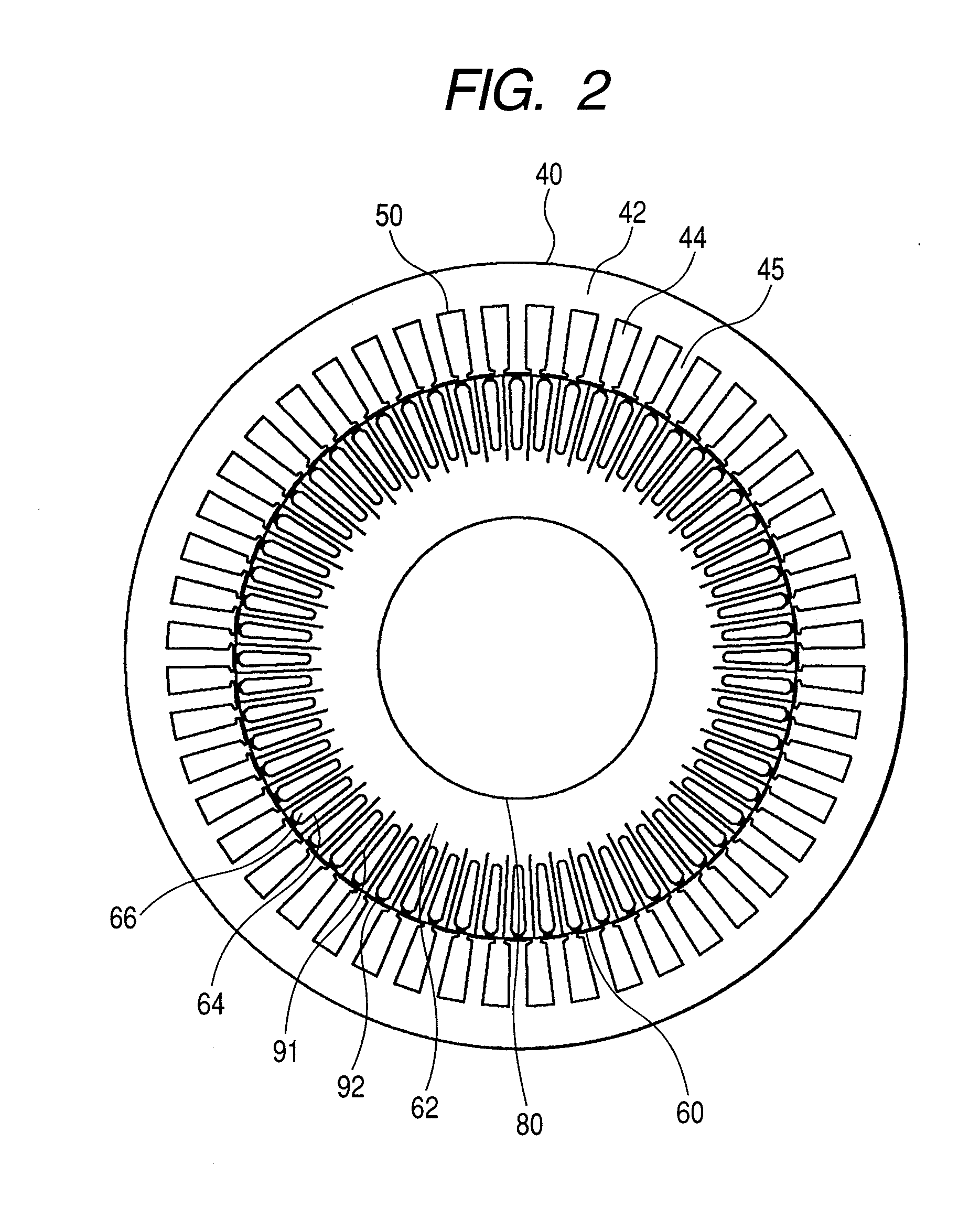
[0020]The stator 40 is comprised of a stator core 42, a multi-phase, for example, a three-phase stator winding 44 wounded on the stator core 42 in the embodiment. An AC current is supplied through a lead wire 46 to the stator winding 44 from an AC terminal (not shown). The stator winding 44 is connect...

embodiment 2

[0132]FIG. 8(a) is a view showing the second embodiment of the present invention. This drawing is a view showing slits 91 and groups of holes 92 of the second embodiment. Since an arrangement other than that of the slits 91 and the groups of holes 92 is the same as the first embodiment, its explanation is omitted in this embodiment (incidentally the same holds true for the others embodiment described latter). The groups of the holes 92 are disposed in laminated magnetic steel sheets respectively so as not to electrically short-circuit between rotor-conductors 66 through a rotor core 62. The groups of the holes 92 of this embodiment are spaced uniformly in a circumferential direction so as to be placed both sides of respective rotor conductors. Furthermore, while pitches of the holes 92 of each group are even, they may be uneven. For example, the more the holes 92 are close to the outer periphery of the rotor core 62, the more the pitches of them may be narrower.

[0133]Additionally, w...

embodiment 3

[0134]FIG. 8(b) is a view showing the third embodiment of the present invention. The present embodiment structures a rotor core 62 so as not to short-circuit between rotor-conductors 66 by disposing holes 92 of each group around each rotor-conductor 66. In this embodiment, while pitches of the holes 92 of each group are even, they may be uneven. For example, the more the holes 92 are close to the outer periphery of the rotor core 62, the more the pitches of them may be narrower.

[0135]Additionally, while the width of each group of holes 92 is set to be monospace, it may be not monospace. For example, the more approaching to outer peripheral surface of the rotor core 62, the width may become wider. Further, in the present embodiment, the diameters of the holes 92 although are even to each other, they may be uneven to each other. For example, the more the holes 92 are close to the outer periphery of the rotor core 62, the diameters of the holes 92 may be larger. In addition, the presen...


PUM


Abstract

An induction machine has a stator and rotor. The stator comprises teeth and slots and stator winding disposed in the slots. The rotor comprises a rotor core having teeth and slots and a rotor-conductor disposed in the rotor slots. Both of the stator core and rotor core are made of laminated steel sheets, and the teeth and slots made of steel sheets are formed by etching.

Description

CLAIM OF PRIORITY[0001]This application claims priority from Japanese application serial No. 2007-083250, filed on Mar. 28, 2007, the content of which is hereby incorporated by reference into this application.BACKGROUND OF THE INVENTION[0002]In connection with a problem on global warming, induction machines are also required to have high efficiency in view of energy conservation. To reduce iron loss of the induction machine, there is a technique that an electric insulation layer is arranged on iron cores. For example, ordinary induction machines are disclosed in Japanese laid open patent publication Sho-55-26040, Sho-56-83252, Hei-03-207228 and Sho-53-98011. Here, any of these disclose air filled holes and slits acting as the electric insulation layer.[0003]The induction machine requires high efficiency. With respect to the high efficiency of the induction machine, decreasing of the iron loss is quite necessary. Here, the iron loss is shown as addition of hysteresis loss and eddy cu...

Claims


Application Information

Patent Timeline
Patent Type & Authority Applications(United States)
IPC IPC(8): H02K17/00H02K3/48H02K1/26H02K1/16
CPCH02K1/06H02K1/16H02K1/26H02K15/024H02K17/165
Inventor NISHIHAMA, KAZUOABE, TERUYOSHIISHIKAWA, YOSHIHISAMIKAMI, HIROYUKI
Owner HITACHI LTD
Why Eureka
Try Eureka