Controller and driver communication for switching regulators

a technology of switching regulators and controllers, applied in the direction of electric variable regulation, process and machine control, instruments, etc., can solve the problems of no controller or gate driver pin available for housing an fccm signal, pcb layout becomes complex, and traces become crowded in a typical spacing limited motherboard

Active Publication Date: 2008-10-02
INTERSIL INC
View PDF4 Cites 47 Cited by
  • Summary
  • Abstract
  • Description
  • Claims
  • Application Information

AI Technical Summary

Benefits of technology

[0023]According to one embodiment of the invention, a method of communicating mode information for operation of a switching regulator between a PWM controller and at least one output stage driver is provided. The driver is coupled to at least one output switch which drives a load. A mode indicating signal is received at the controller, wherein the mode indicating signal is operable to indicate intervals of time when the load is in a low power mode. Based on the mode indicating signal, it is determined when the load is in the low power mode. Responsive to the determining, the controller generates a PWM signal encoded with mode information referred to herein as a PWM mode signal. The PWM mode signal comprises at least three (3) different levels including at least one intermediate level. The PWM mode signal is coupled to the input of the driver. Based on the PWM mode signal, the regulator is switched into at least one low power operational mode. The low power operational mode can comprise diode emulation mode (DEM), phase dropping mode and a diode braking mode.
[0024]A transition of the PWM mode signal between a high or low level and the intermediate level can be used for triggering said switching. For example, diode braking can be initiated when the PWM mode signal transitions from the high level to the intermediate level.
[0025]The PWM mode signal can comprise a repetitive pattern which begins at a transition from a high level to a low level, reaches the intermediate level after a first time, and transitions from the intermediate level to the high level at a second time, the second time after the first time.

Problems solved by technology

In the case the controller and gate drivers are on separate chips, as the number of phases increases, the PCB layout becomes complex and traces becomes crowded in a typical spacing limited motherboard.
As a result, there may be no controller or gate driver pin available for accommodation of an FCCM signal.
A dedicated FCCM pin and the required signaling to implement DEM increases the pin count for both the controller and the driver as well as the layout complexity.

Method used


Image

  • Controller and driver communication for switching regulators
  • Controller and driver communication for switching regulators
  • Controller and driver communication for switching regulators

Examples


Embodiment Construction

[0029]Embodiments of the present invention are more particularly described in the following description and examples that are intended to be illustrative only since numerous modifications and variations therein will be apparent to those of ordinary skill in the art. As used in the specification and in the claims, the singular form “a,”“an,” and “the” may include plural referents unless the context clearly dictates otherwise. Also, as used in the specification and in the claims, the term “comprising” may include the embodiments “consisting of” and “consisting essentially of”.

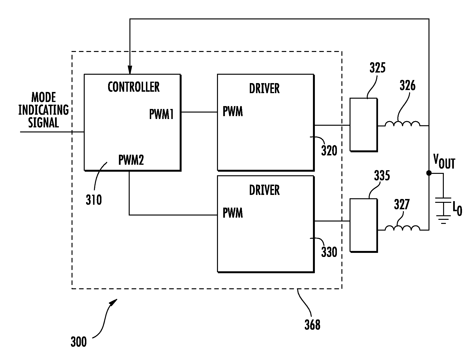
[0030]In various embodiments of the present invention, an improved method and related controller and gate driver architecture for communicating mode information between a PWM controller and one or more gate drivers is provided. Methods according to embodiments of the invention comprise providing a PWM controller having at least one PWM output coupled to an input of at least one gate driver. The controller is oper...


PUM


Abstract

Pulse width modulation (PWM) controllers and output stage driver circuits and related methods of communicating switching regulator mode information. The controller includes circuitry that recognizes intervals when the load driven by the regulator is in a low power mode. Responsive to recognizing the low power mode, the controller generates a PWM mode signal having at least three (3) different levels including at least one intermediate level that is coupled to at least one driver. Based on the PWM mode signal, the regulator is switched into a power saving low power operational mode.

Description

CROSS-REFERENCE TO RELATED APPLICATIONS[0001]This application claims priority to Provisional Application No. 60 / 908,539 entitled “SIMPLIFIED DIODE EMULATION HANDSHAKE BETWEEN CONTROLLER AND DRIVER METHOD AND ARCHITECTURES” filed on Mar. 28, 2007, which is incorporated by reference in its entirety into the present application.BACKGROUND OF THE INVENTION[0002]It is known to improve synchronous switching voltage regulator efficiency at light load conditions to have the regulator operate under diode emulation mode (DEM). With DEM enabled, the bottom-side MOSFET switch is disabled preventing negative current flow from the output inductor during low load operation. Under heavy loads, the voltage regulator operates under forced continuous conduction mode (FCCM). In FCCM, the controller always operates as a synchronous rectifier, switching the bottom-side MOSFET regardless of the output load. Thus, in FCCM, the inductor current flows in both directions.[0003]FIG. 1 is a block diagram schema...

Claims


Application Information

Patent Timeline
Patent Type & Authority Applications(United States)
IPC IPC(8): G05F1/10G05F1/00
CPCH02M3/1584H02M2001/0032Y02B70/16Y02B70/1466H02M3/1588H02M1/0032Y02B70/10
Inventor CHEUNG, CHUNQIU, WEIHONGISHAM, ROBERT
Owner INTERSIL INC
Why Eureka
Try Eureka