Differential signaling system and flat panel display with the same

a signaling system and flat panel technology, applied in the field can solve the problems of increasing testing costs, deteriorating image quality of flat panel displays, and being suitable for miniaturization and light weight requirements of smaller electronic devices, so as to achieve accurate impedance matching, improve testing efficiency, and improve the effect of accuracy

Inactive Publication Date: 2008-10-02
SAMSUNG DISPLAY CO LTD
View PDF26 Cites 16 Cited by
  • Summary
  • Abstract
  • Description
  • Claims
  • Application Information

AI Technical Summary

Benefits of technology

[0021]Accordingly, it is an aspect of the present invention to provide a differential signaling system which may clearly detect a presence of an impedance matching by a test circuit in a flat panel display that uses a differential signal transmission method and to more accurately perform the impedance matching through the detection thereof in order to stably transmit a high speed signal without an electro magnetic interference, wherein the test circuit detects a variation of a differential impedance and converts the amplified signal into a direct current component, to thereby easily detect the presence of the impedance matching, and a flat panel display with the same.
[0022]It is another aspect of the present invention is to provide a differential signaling system, which measures a skew, time delay, and / or a phase difference of a differential signal inputted to or transmitted in the differential transmission line, to measure time delay of the signal due to a variation of an impedance in the differential transmission line, so that an impedance matching is more accurately performed through the measurement thereof in order to stably transmit a high speed signal without an electro magnetic interference, and a flat panel display with the same.

Problems solved by technology

However, since the CRT is heavy and large, it is not suitable to miniaturization and light-weight requirements of smaller electronic devices.
Also, the electro magnetic interference (EMI) deteriorates an image quality of the flat panel display.
However, since a typical method for detecting the minute variation in the differential impedance Zdiff has a long measuring time and uses measuring equipment of high cost, its disadvantages include increased testing cost and low detection rate for a minute variation in the differential impedance Zdiff.

Method used


Image

  • Differential signaling system and flat panel display with the same
  • Differential signaling system and flat panel display with the same
  • Differential signaling system and flat panel display with the same

Examples


Embodiment Construction

[0038]Reference will now be made in detail to the aspects of the present invention, examples of which are illustrated in the accompanying drawings, wherein like reference numerals refer to the like elements throughout. The aspects are described below in order to explain the present invention by referring to the figures.

[0039]Here, when one element is coupled to another element, the one element may be not only directly coupled to another element but also indirectly coupled to another element via yet another element. Further, some elements are not shown for clarity. Also, like reference numerals refer to like elements throughout.

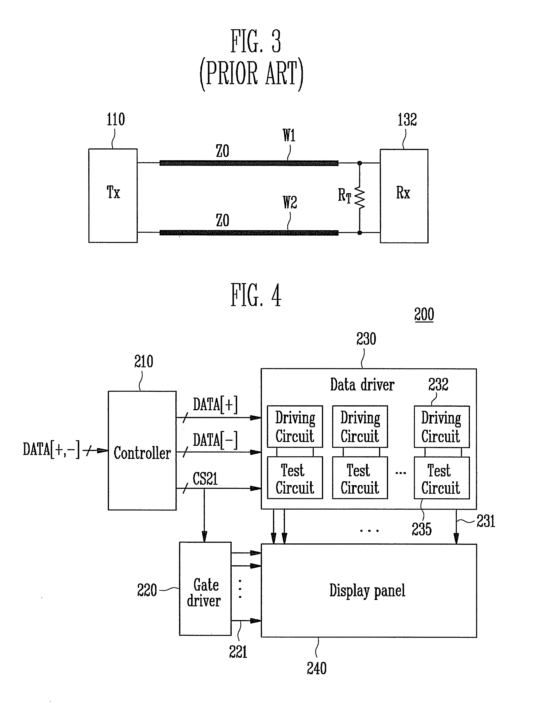
[0040]FIG. 4 is a block diagram showing a composition of a flat panel display 200 according to an aspect of the present invention. With reference to FIG. 4, the flat panel display 200 includes a display panel 240, a gate driver 220, a data driver 230, and a controller 210. Gate lines (or wirings) 221 and data lines (or wirings) 231 are arranged to intersect ea...


PUM


Abstract

A differential signaling system, wherein a first wiring and a second wiring are coupled between a sending end and a receiving end as a differential signal line. A termination resistor is coupled between the first wiring and the second wiring in the receiving end side. A test circuit is coupled to the termination resistor in parallel, and amplifies and detects a variation of a differential impedance due to the differential signal line. The test circuit includes: a differential test amplifier for amplifying a variation in the differential impedance of the first wiring or the second wiring; a switching unit installed at an input terminal of the differential test amplifier for controlling an operation of the differential test amplifier; and a peak detector for converting an output signal of the differential test amplifier into a direct current component; and a phase detector for detecting a skew, a time delay, and / or a phase difference of a signal inputted to the differential signal line.

Description

CROSS-REFERENCE TO RELATED APPLICATION[0001]This application claims the benefit of Korean Application No. 2007-32573, filed Apr. 2, 2007, in the Korean Intellectual Property Office, the disclosure of which is incorporated herein by reference.BACKGROUND OF THE INVENTION[0002]1. Field of the Invention[0003]Aspects of the present invention relate to a flat panel display that uses a signal transmission method that transmits a differential signal, and more particularly to a flat panel display that includes a differential signaling system for matching impedance in the signal transmission method.[0004]2. Description of the Related Art[0005]In general, a cathode ray tube (CRT) is one of display devices which have been in wide use as a monitor for a television, a measuring instrument, or an information terminal. However, since the CRT is heavy and large, it is not suitable to miniaturization and light-weight requirements of smaller electronic devices.[0006]Accordingly, in order to replace th...

Claims


Application Information

Patent Timeline
Patent Type & Authority Applications(United States)
IPC IPC(8): G01R27/32G09G3/00
CPCG09G3/006G09G3/2092G09G5/006G09G2320/0233G09G2330/028G09G2330/06G09G3/20H03H11/16H03H11/28H04B3/50
Inventor RYU, JEE-YOUL
Owner SAMSUNG DISPLAY CO LTD
Why Eureka
Try Eureka