Voltage-controlled oscillator and method of operating the same

a voltage control and oscillator technology, applied in the direction of oscillator, electrical equipment, etc., can solve the problems of difficulty in realizing the oscillation frequency required in a device or an application by controlling the control voltage, and achieve the effect of expanding the variable range of the oscillation frequency

Inactive Publication Date: 2008-10-02
NEC ELECTRONICS CORP
View PDF4 Cites 13 Cited by
  • Summary
  • Abstract
  • Description
  • Claims
  • Application Information

AI Technical Summary

Benefits of technology

[0021]According to the present invention, it is possible to enlarge the v...

Problems solved by technology

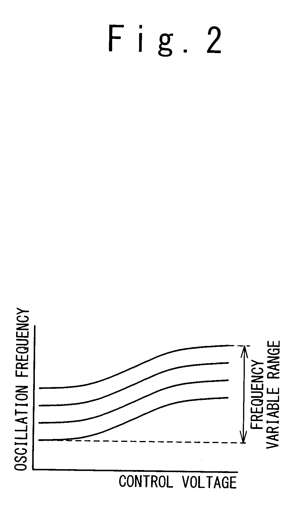
That is, it is difficult to realize an oscillation frequency required in a device or an application by controlling the control voltage, since the changes in the oscillation frequency corresponding to the changes in the control voltage are small.
However, ...

Method used


Image

  • Voltage-controlled oscillator and method of operating the same
  • Voltage-controlled oscillator and method of operating the same
  • Voltage-controlled oscillator and method of operating the same

Examples


Embodiment Construction

[0031]The invention will be now described herein with reference to illustrative embodiments. Those skilled in the art will recognize that many alternative embodiments can be accomplished using the teachings of the present invention and that the invention is not limited to the embodiments illustrated for explanatory purposed.

1. Configuration of PLL Circuit

[0032]FIG. 3 is a block diagram showing a configuration example of a PLL circuit 1000 according to the present embodiment. The PLL circuit 1000 shown in FIG. 3 is provided with a voltage-controlled oscillator 100, a reference frequency oscillator 101, a reference frequency divider 102, a comparison frequency divider 103, a phase comparator 104, a loop filter 105 and an output buffer 108. The voltage-controlled oscillator 100 includes a voltage-controlled oscillation circuit 106 and a selection circuit 107.

[0033]The reference frequency oscillator 101 is a highly stable oscillator such as a crystal oscillator and outputs a clock signa...


PUM


Abstract

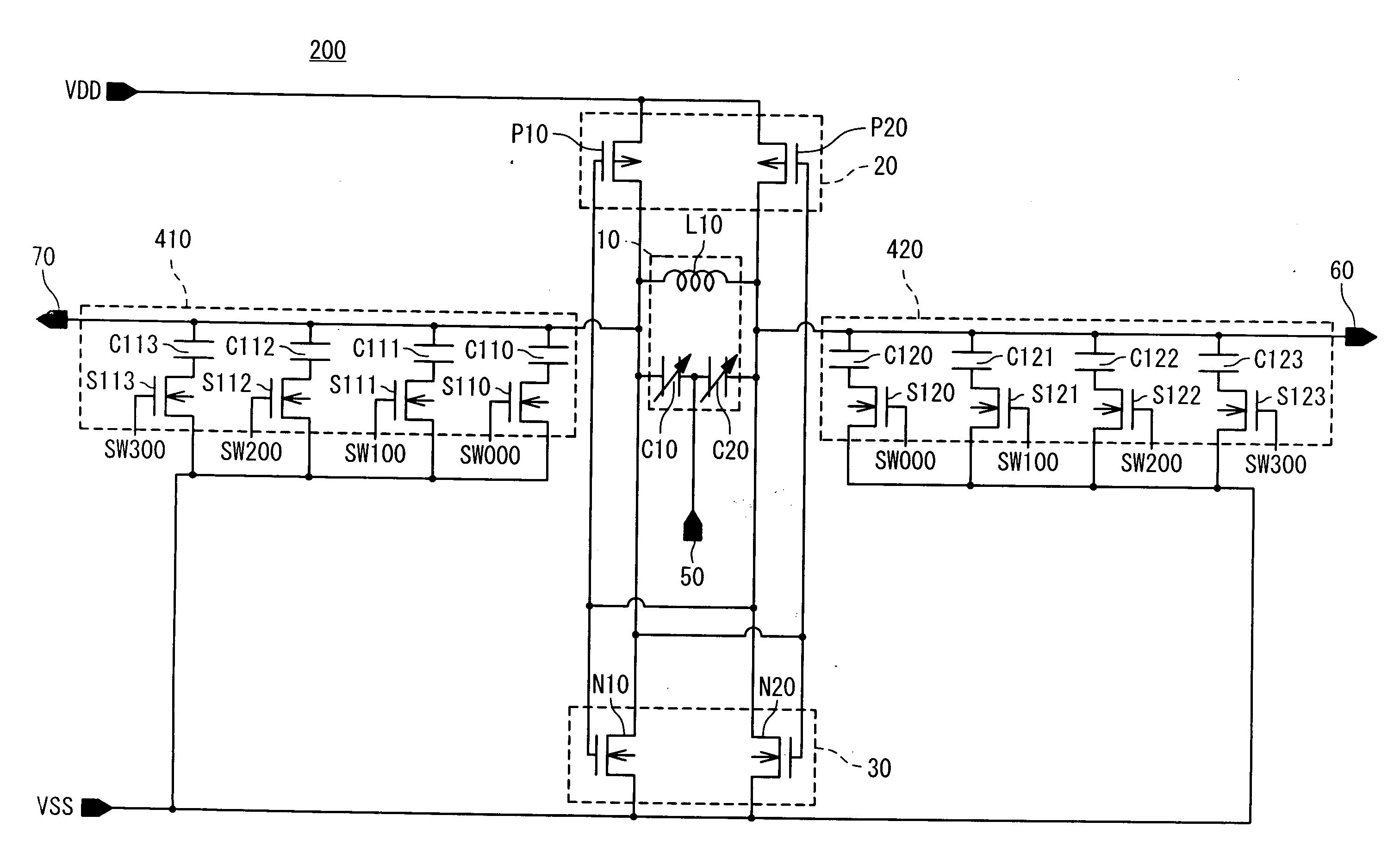
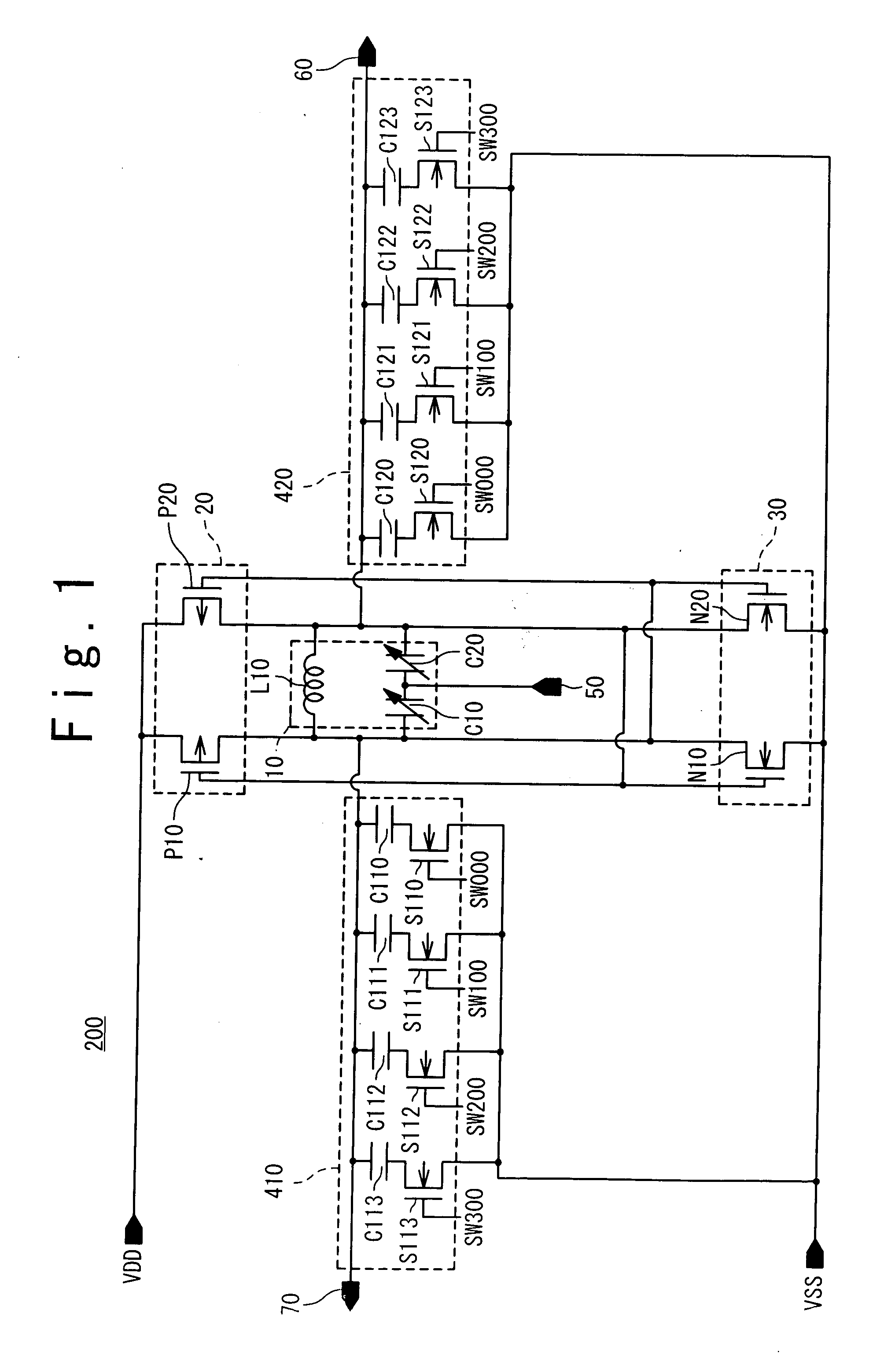
A voltage-controlled oscillator has: an LC resonant circuit including an inductor and a variable capacitor that are connected in parallel between a pair of output terminals; a plurality of negative resistance circuits provided between a power source and the LC resonant circuit; a plurality of capacitor groups; a first switch circuit selecting an arbitrary number of negative resistance circuit from the plurality of negative resistance circuits; and a second switch circuit selecting an arbitrary number of capacitor group from the plurality of capacitor groups. The LC resonant circuit and the selected capacitor group constitute a resonant circuit. The resonant circuit is electrically connected to the power source through the selected negative resistance circuit, oscillates at an oscillation frequency depending on total capacitance of the resonant circuit, and outputs a differential signal of the oscillation frequency from the pair of output terminals.

Description

BACKGROUND OF THE INVENTION[0001]1. Field of the Invention[0002]The present invention relates to a voltage-controlled oscillator (VCO). In particular, the present invention relates to a voltage-controlled oscillator utilizing an LC resonant circuit.[0003]This application is based upon and claims the benefit of priority from Japanese patent application No. 2007-094501, filed on Mar. 30, 2007, the disclosure of which is incorporated herein in its entirely by reference.[0004]2. Description of Related Art[0005]A PLL (Phase Locked Loop) circuit is capable of outputting an output signal whose frequency is an integral multiple of a frequency of an input signal. For example, the PLL circuit is applied to a micro processor and used for generating an internal clock whose frequency is an integral multiple of an external clock frequency to speed up the micro processor. Also, many high-speed devices such as a SerDes (Serializer / Deserializer) employ the PLL circuit.[0006]The PLL circuit includes ...

Claims


Application Information

Patent Timeline
IPC IPC(8): H03B7/00
CPCH03B5/1228H03B5/1212H03B5/1221H03B5/1265H03B5/124
Inventor SHIBATA, TORU
Owner NEC ELECTRONICS CORP
Why Eureka
Try Eureka