Liquid circulation apparatus, image forming apparatus and liquid circulation method

a liquid circulation and image forming technology, applied in printing, inking apparatus, other printing apparatus, etc., can solve the problems of displacement of the dot position on the print medium, failure of ejection, and increase of the fluid resistance inside the nozzle, so as to prevent ejection defects, increase the liquid circulation volume, and increase the viscosity

Inactive Publication Date: 2008-10-02
FUJIFILM CORP
View PDF9 Cites 121 Cited by
  • Summary
  • Abstract
  • Description
  • Claims
  • Application Information

AI Technical Summary

Benefits of technology

[0052]According to the present invention, the liquid circulation volume is controlled by adjusting the liquid supply volume in accordance with the liquid ejection volume of the plurality of liquid droplet ejection elements. By this means, when the liquid ejection volume is low, it is possible to increase the liquid circulation volume and thereby prevent ejection defects caused by increase in the viscosity of the liquid in the vicinity of the nozzles. On the other hand, when the liquid ejection volume is high, then by lowering the liquid circulation volume (and desirably, redu

Problems solved by technology

When the ink viscosity in the vicinity of the nozzles rises, then the fluid resistance inside the nozzles becomes greater, and ejection defects arise due to the occurrence of variations in the volume of the ejected ink droplets or in the direction of flight of the droplets, or ejection failures may occur.
Consequently, this may give rise to displacement of the dot positions on the print medium, error in the size of the dots, and omission of dots.
If this situation proceeds further, then it becomes impossible to perform ejection completely, and maintenance known as “nozzle cleaning” becomes necessary.
In response to this, according to experimentation carried out by the present inventors and others, it has been confirmed that in a state where no particular countermeasures are implemented, then in the case of an ink which uses water as a solvent, the solvent starts to evaporate from the nozzles and within five or six seconds, ejection defects arise and extremely serious problems occur even under conditions of normal temperature and normal pressure.
However, even with this method, if a long period of time elapses, then there is a decline in the concentration of ink solvent in the whole of the pressure chambers and the nozzle sections, and consequently, this can lead to ejection defects.
In a head based on a thermal method in which it is difficult to mix up the ink by applying a vibration of a level that does not cause ejection, to the ink, as described above, the ejection force is inherently a strong force, and therefore it takes a long time until ejection defects such as those described above arise.
However if left without taking any particular countermeasures, ejection defects will arise, and therefore control is implemented in a similar fashion in order to expel ink which has risen in viscosity in the vicinity of the nozzles.
However, in order completely to prevent increase in the viscosity of the ink in the vicinity of the nozzles by means of this method, it is necessary for the length from the supply path to the nozzle, via the pressure chamber, to be no more than several tens of microns, and therefore, in practice, the increase in viscosity is not suppressed completely, and control for expelling ink of

Method used


Image

  • Liquid circulation apparatus, image forming apparatus and liquid circulation method
  • Liquid circulation apparatus, image forming apparatus and liquid circulation method
  • Liquid circulation apparatus, image forming apparatus and liquid circulation method

Examples


first embodiment

General Composition of Inkjet Recording Apparatus

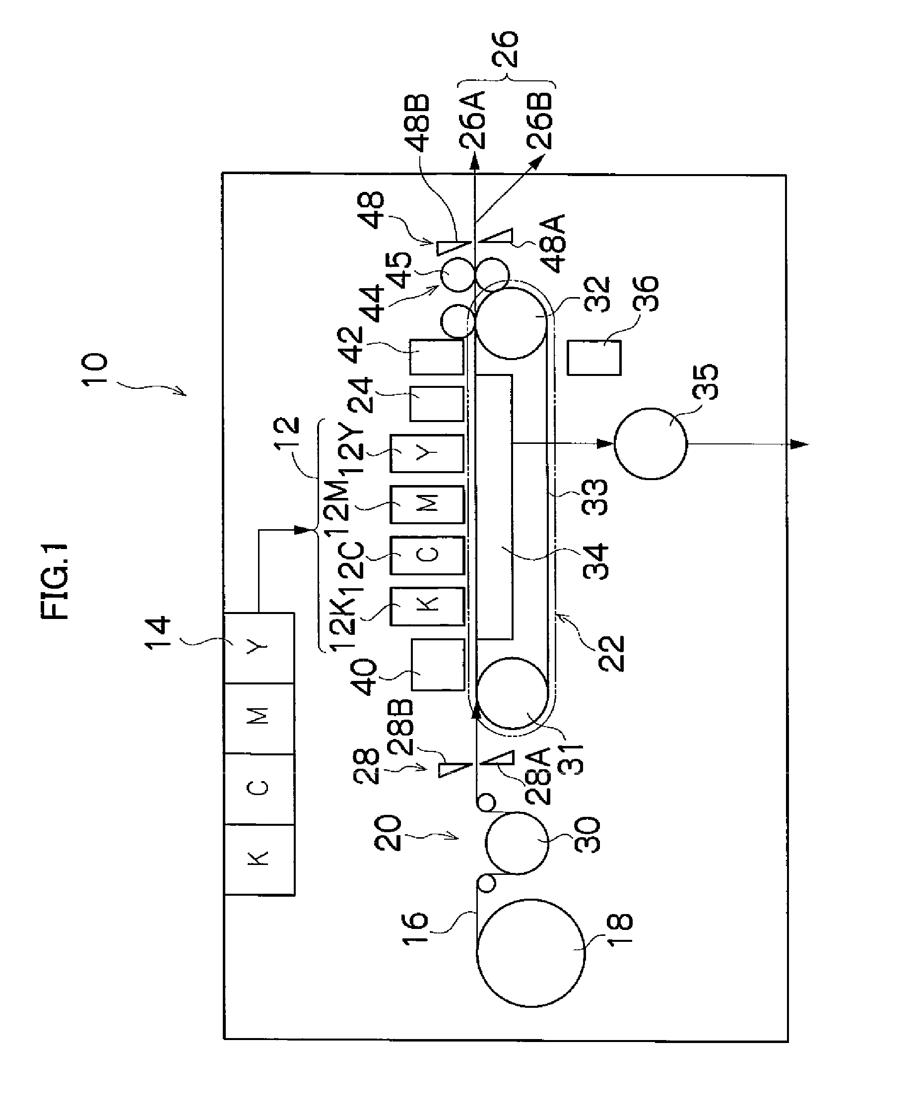
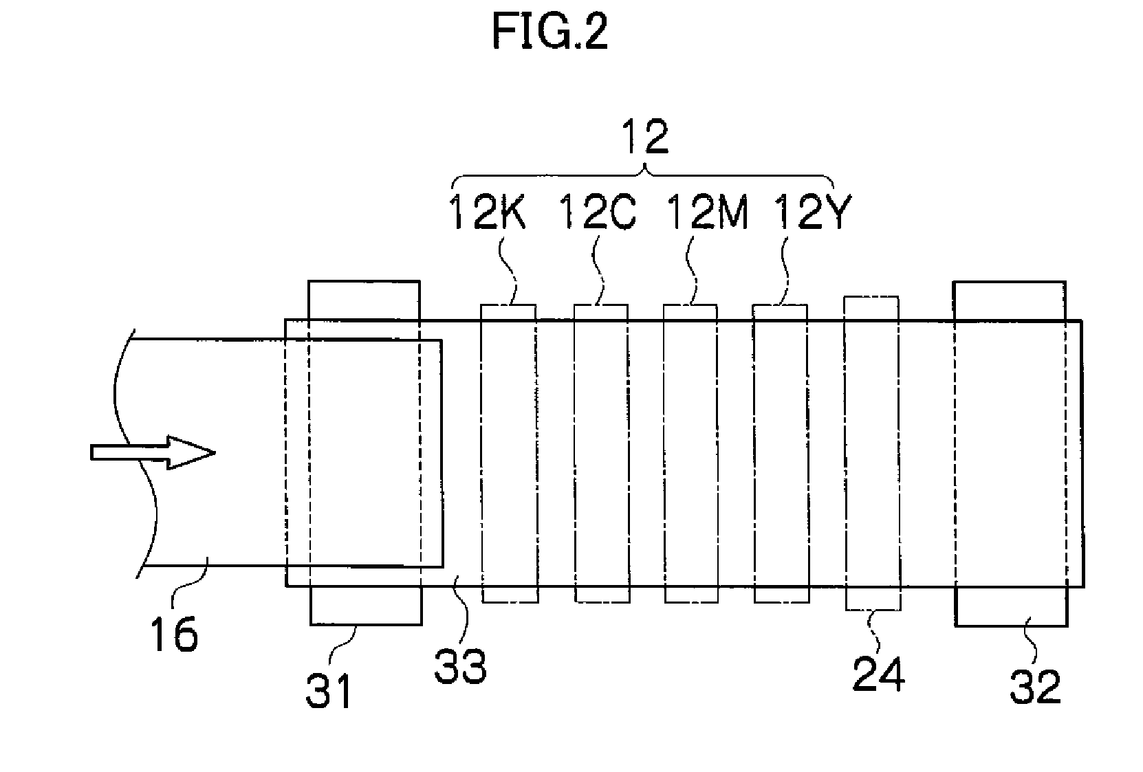
[0072]Firstly, an inkjet recording apparatus which forms an image forming apparatus according to an embodiment of the present invention will be described. FIG. 1 is a general schematic drawing showing a general view of an inkjet recording apparatus according to an embodiment of the present invention. As shown in FIG. 1, the inkjet recording apparatus 10 comprises: a print unit 12 having a plurality of recording heads 12K, 12C, 12M, and 12Y for ink colors of black (K), cyan (C), magenta (M), and yellow (Y), respectively; an ink storing and loading unit 14 for storing inks of K, C, M and Y to be supplied to the recording heads 12K, 12C, 12M, and 12Y; a paper supply unit 18 for supplying recording paper 16; a decurling unit 20 for removing curl in the recording paper 16; a suction belt conveyance unit 22 disposed facing ink-droplet ejection face (the nozzle face) of the print unit 12, for conveying the recording paper 16 while keeping th...

second embodiment

[0196]Next, a second embodiment of the present invention will be described. Below, portions which are common with the first embodiment are not explained further, and the following description centers particularly on characteristic features of the second embodiment.

[0197]FIG. 12 is an oblique diagram showing a three-dimensional view of the periphery of a pressure chamber in a recording head according to the second embodiment. FIG. 13 is a plan diagram showing the detailed composition of the recording head according to the second embodiment. FIG. 14 is a cross-sectional diagram showing one portion of a second recording head (a cross-sectional view along line 14-14 in FIG. 13). In FIGS. 12 to 14, parts which are the same as those in FIGS. 5 to 7 are labeled with the same reference numerals.

[0198]The second embodiment is the same as the first embodiment except that the second embodiment is different from the first embodiment in respect of the connection arrangement of the individual cir...

third embodiment

[0200]Next, a third embodiment of the present invention will be described. Below, portions which are common with the first and second embodiments described above are not explained further, and the following description centers on characteristic features of the third embodiment.

[0201]FIG. 15 is a plan diagram showing the detailed composition of the recording head according to the third embodiment. FIG. 16 is a cross-sectional diagram showing one portion of the recording head according to the third embodiment (a cross-sectional view along line 15-15 in FIG. 16). As shown in FIGS. 15 and 16, in the recording head 50C according to the present embodiment, the pressure chambers 58A and 58B which are mutually opposing are joined together by means of an individual circulation channel 72, and a pressure differential (back pressure differential) is applied between the pressure chambers 58A and 58B, thereby causing ink to circulate from the pressure chamber 58A on the high pressure side, throu...


PUM


Abstract

A liquid circulation apparatus includes: a plurality of liquid ejection elements each of which includes a nozzle, a pressure chamber which is connected to the nozzle and accommodates liquid, and a piezoelectric element which displaces a wall of the pressure chamber to eject the liquid in the pressure chamber through the nozzle; a plurality of individual supply channels which are respectively connected to the liquid ejection elements; a common supply channel which is connected to the individual supply channels, the liquid being supplied from the common supply channel to the liquid ejection elements through the individual supply channels; a plurality of individual circulation channels which are respectively connected to the liquid ejection elements; a common circulation channel which is connected to the individual circulation channels, the liquid being circulated from the liquid ejection elements to the common circulation channel through the individual circulation channels; and a control device which controls a circulation volume of the liquid circulated from the liquid ejection elements to the common circulation channel, by adjusting a supply volume of the liquid supplied from the common supply channel to the liquid ejection elements in accordance with an ejection volume of the liquid ejected from the liquid ejection elements.

Description

BACKGROUND OF THE INVENTION[0001]1. Field of the Invention[0002]The present invention relates to a liquid circulation apparatus, an image forming apparatus and a liquid circulation method, and more particularly, to technology for circulating liquid in the vicinity of a plurality of nozzles of a liquid ejection head which ejects ink droplets from the nozzles.[0003]2. Description of the Related Art[0004]An inkjet recording apparatus has been known which performs recording by ejecting ink droplets toward a recording medium from a plurality of nozzles which are formed in an inkjet head (hereinafter, called a “recording head” or simply “head”). The inkjet recording apparatus has been commonly used because of its little noise during operation, low running cost and capability of recording a high quality image on a wide variety of recording medium. The ink ejection method may be a piezoelectric method in which ink droplets are ejected from nozzles by utilizing the displacement of piezoelect...

Claims


Application Information

Patent Timeline
IPC IPC(8): B41J2/175B41J29/38B41J2/045
CPCB41J2/14233B41J2/175B41J11/007B41J11/0085B41J29/38B41J2002/14241B41J2002/14467B41J2202/12
Inventor NAGASHIMA, KANJIKYOSO, TADASHIKUSAKARI, TSUTOMU
Owner FUJIFILM CORP
Why Eureka
Try Eureka