
Camera

a technology of interchangeable lenses and cameras, applied in the field of cameras, can solve the problems of excessive large amount of distortion aberration data, image distortion occurring in pictures, etc., and achieve the effect of accurately correcting image distortion and restricting the amount of data necessary for distortion correction

Inactive Publication Date: 2008-10-02
ASAHI KOGAKU KOGYO KK
View PDF11 Cites 23 Cited by
  • Summary
  • Abstract
  • Description
  • Claims
  • Application Information

AI Technical Summary

Benefits of technology

[0006]An object of the present invention is to provide a camera, apparatus, and method for correcting distortion, and a computer program that is capable of correcting image distortion accurately while restricting the amount of data necessary for distortion correction.

Problems solved by technology

In a camera, image distortion occurs in a picture due to the characteristics of an optical lens.
For example, the distortion correction process is carried out within the focal mange of a zoom (telephoto) lens that produces a large degree of distortion.
Consequently, the amount of distortion aberration data necessary for correcting the distortion becomes excessively large.
In particular, in the case of a camera equipped with an interchangeable lens unit, ouch as an SLR-type camera, distortion aberration data must be prepared for attachable lenses at all focal lengths, resulting in a further increase in the distortion aberration data that must be stored.

Method used


Image

  • Camera
  • Camera
  • Camera

Examples


first embodiment

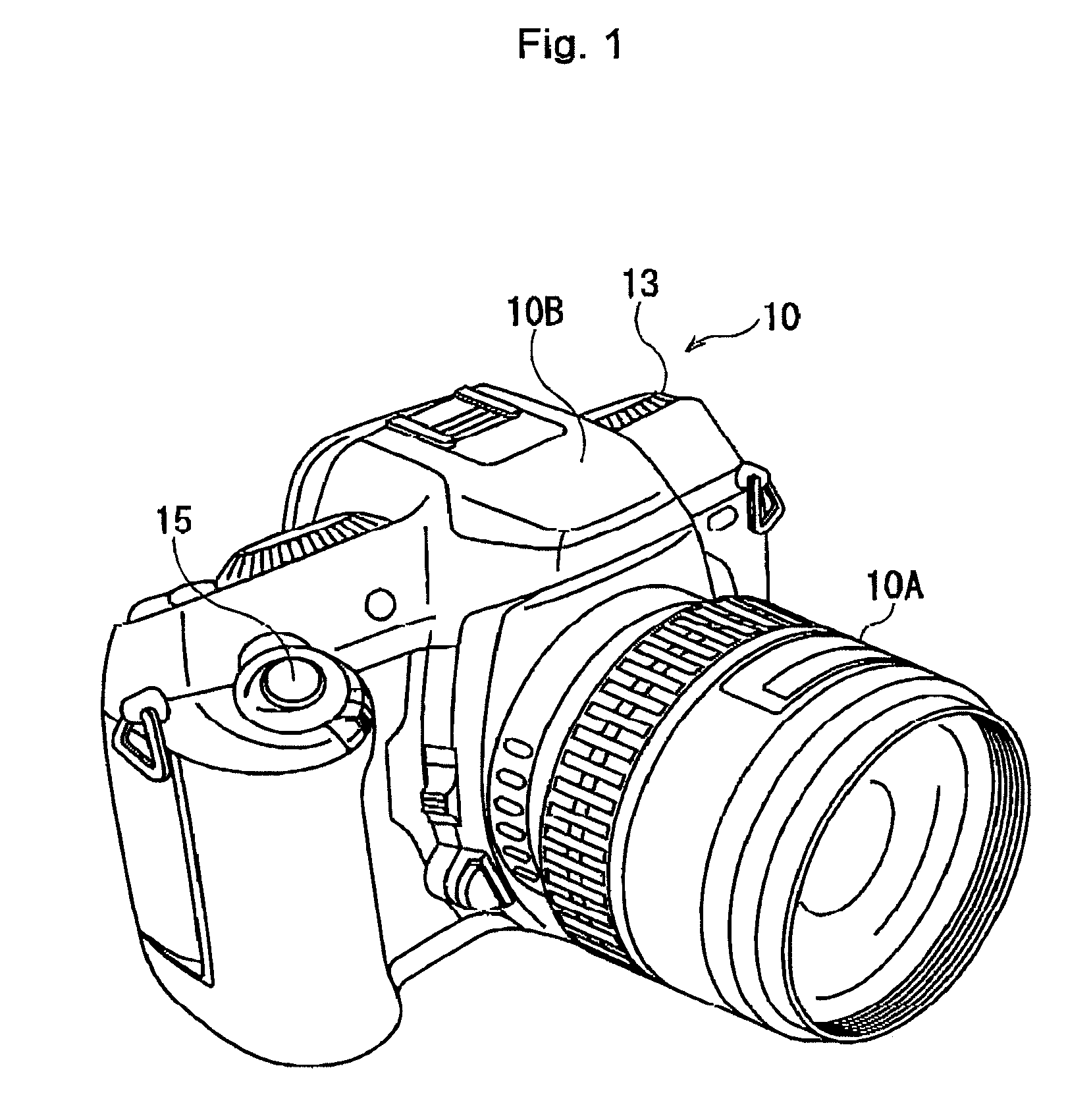
[0027]FIG. 1 is a schematic perspective view of a digital camera according to a

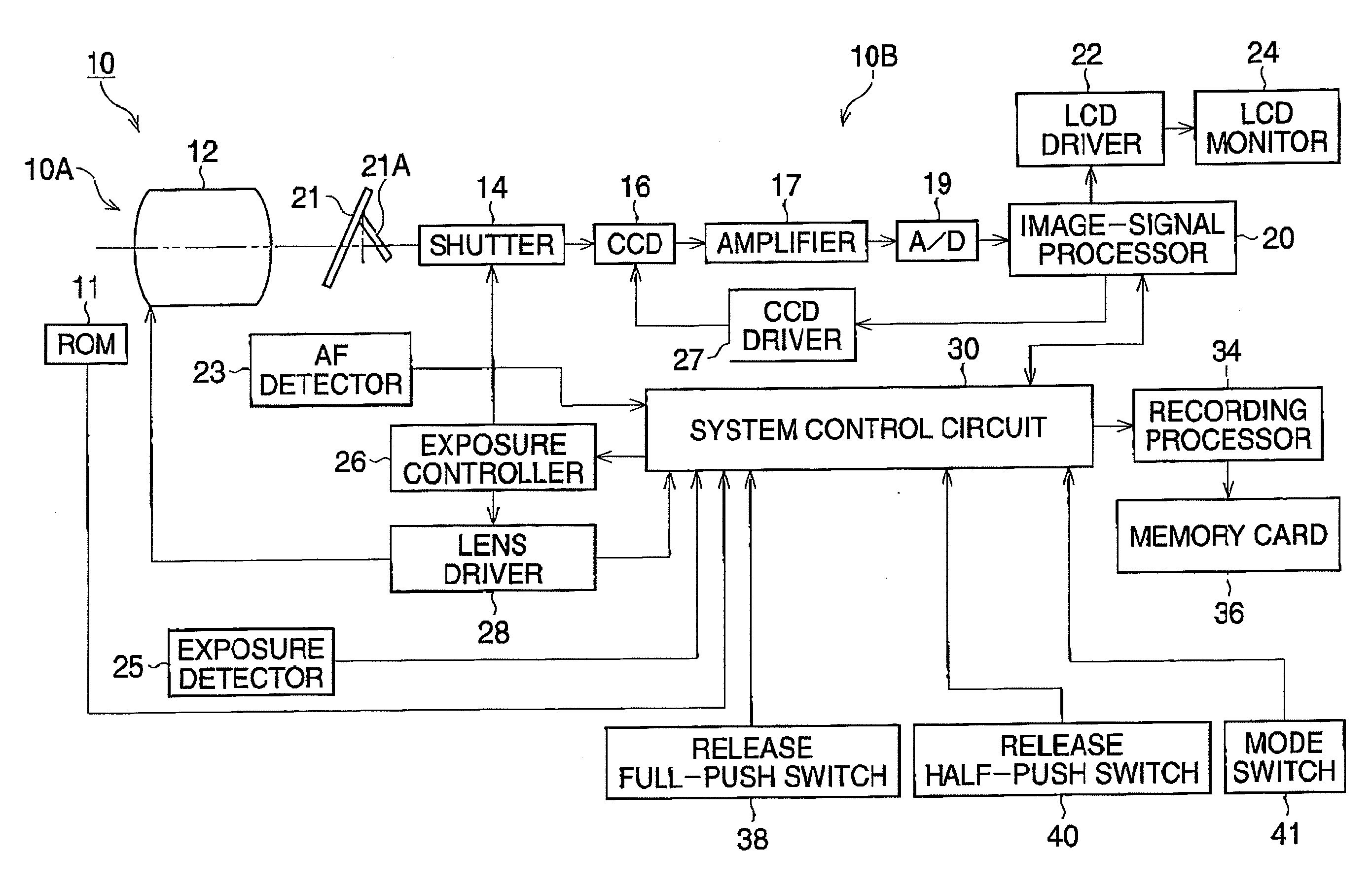
[0028]An SLR-type digital camera 10 is equipped with an interchangeable lens unit 10A, which is removably attached to a camera body 10B. A release button 15 is operated by the user to take a picture, and a mode dial 13 is operated to set picture mode or playback mode. In the lens unit 10A, a photographic optical system (not shown) with a zoom lens is provided. Zooming can be performed in AF (Auto Focus) mode or MF (Manual Focus) mode.

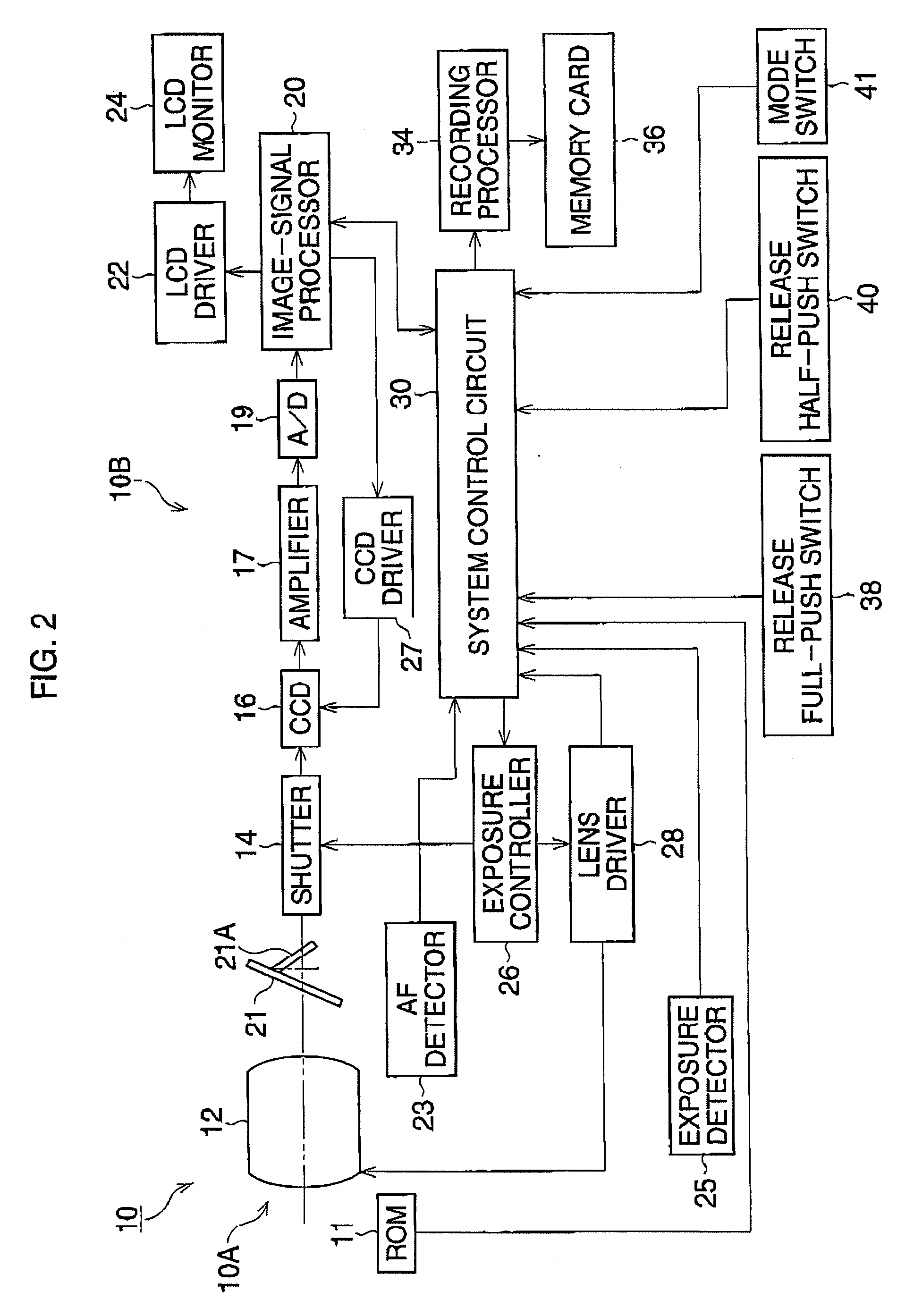
[0029]FIG. 2 is a block diagram of the digital camera 10 according to the present embodiment.

[0030]The digital camera 10 is equipped with an image-signal processor 20 and a system control circuit 30, and a memory card 36 is removably installed in the camera body 10B. The system control circuit 30, including a CPU, a ROM unit and a RAM unit, connects with a release full-push switch 38, a release half-push switch 40, and a mode switch 41. The system control circuit 30 detects a...

second embodiment

[0065]In the second embodiment, the number “m” of sample values of image heights and corresponding distortion aberrations is stored in the ROM 11. For example, three sample values of image heights and distortion aberrations as shown in the following table are stored. The sample values are measured in advance at approximately 5 mm intervals, and these sample values are prepared for each focal length.

123IMAGE HEIGHT (mm)51014.2DISTORTION0.1670.6951.493ABERRATION (%)

[0066]When a picture is taken, the number “m” of image heights and distortion aberrations is selected according to focal length, and a linear approximation function is defined from plots of the selected sample data. As shown an FIG. 9, the linear approximation function is defined by joining the plots. Based on this linear approximation function, the distortion aberration D is calculated at each image height, i.e., for each pixel. Then, the distortion correction process shown in FIG. 7 is carried out.

[0067]As shown in FIG. 1...


PUM


Abstract

A camera according has an interchangeable lens unit removably attached to a camera body, and an image-generating processor that generates image data of a subject captured by the lens unit. A memory provided in the lens unit stores distortion data. The distortion data is associated with an approximation function, which represents the correspondence relationship between image height and distortion aberration. The distortion data includes at least one of: coefficient data of the approximation function, and sample data of the image height and the corresponding distortion aberration. Furthermore, the camera has an approximation function processor that defines an approximation function used to process the image data on the basis of the distortion data read from the memory, and a distortion correction processor that carries out distortion correction processing on the image data based on the aberration distortion calculated for each image point by the defined approximation function.

Description

BACKGROUND OF THE INVENTION[0001]1. Field of the Invention[0002]The present invention relates to a camera with an interchangeable lens, such as an SLR (Single Lens Reflex) camera. In particular, it relates to a camera with a distortion-correction function.[0003]2. Description of the Related Art[0004]In a camera, image distortion occurs in a picture due to the characteristics of an optical lens. Distortion aberration varies with the lens's position along the optical axis. For example, the distortion aberration at a telephoto angle is different from that at a wide angle. In a digital camera, image distortion can be corrected by the image correction process, wherein the coordinate information of image points, i.e., individual pixels, is modified by utilizing aberration data measured in advance. For example, the distortion correction process is carried out within the focal mange of a zoom (telephoto) lens that produces a large degree of distortion. Also, an image may be divided into a p...

Claims


Application Information

Patent Timeline
IPC IPC(8): H04N5/76H04N5/217G03B17/14G06T3/00H04N5/232H04N101/00
CPCH04N5/217H04N5/23209H04N5/3572H04N5/772H04N5/907H04N9/8047H04N23/81H04N23/663H04N23/672H04N25/61
Inventor ABE, NOBUAKI
Owner ASAHI KOGAKU KOGYO KK
Learn More