Optical direct amplifier for WDM optical transmission

a direct amplifier and optical transmission technology, applied in electromagnetic transmission, electromagnetic transmission, semiconductor lasers, etc., can solve the problems of excessive power consumption of individual optical devices used in wdm optical transmission systems, deterioration of transmission characteristics, and increase in electric power consumption, so as to achieve efficient transmission and simple and low-cost structure

Inactive Publication Date: 2008-10-02
NEC CORP
View PDF12 Cites 17 Cited by
  • Summary
  • Abstract
  • Description
  • Claims
  • Application Information

AI Technical Summary

Benefits of technology

[0034]In another preferred embodiment of the amplifier according to the invention, a thermoelectric effect element is used as the heat transmission regulator. In this embodiment, there is an additional advantage that the heat transmission regulator can be realized with a simple and low-cost structure.
[0035]In still another preferred embodiment of the amplifier according to the invention, the thermoelectric effect element is formed to be plate-shaped, and one surface of the thermoelectric effect element is in close contact with the heat radiating member while another surface of the thermoelectric effect element is in close contact with the optical amplification medium. In this embodiment, there is an additional advantage that the heat is efficiently transmitted from the heat radiating member to the optical amplification medium by way of the heat transmission regulator.
[0036]In a further preferred embodiment of the amplifier according to the invention, a heater for heating the optical amplification medium is additionally provided. In this embodiment, there is an additional advantage that the said optical direct amplifier can be used even if it is difficult to maintain the optical amplification medium at a predetermined temperature higher than an ambient temperature utilizing the heat generated by the exciting light source due to such a reason as the ambient temperature being extremely low.
[0037]In a still further preferred embodiment of the amplifier according to the invention, the optical amplification medium is formed by an optical fiber. In this embodiment, there is an additional advantage that the advantages of the invention are exhibited prominently.
[0038]In a still further preferred embodiment of the amplifier according to the invention, the temperature controller is configured in such a way as to maintain the temperature of the optical amplification medium at a predetermined temperature higher than an ambient temperature. In this embodiment, there is an additional advantage that the advantages of the invention are exhibited prominently.
[0039]In a still further preferred embodiment of the amplifier according to the invention, the said amplifier is configured for WDM optical transmission. In this embodiment, there is an additional advantage that the advantages of the invention are exhibited prominently.

Problems solved by technology

In recent years, with the WDM optical transmission system, electric power consumption has been increasing due to the performance enhancement of optical components or devices such as optical cross connects, the speedup in the operation of optical transmitters / receivers for aiming at realization of the transmission of optical signals at 40 Gbit / s, and so on.
For this reason, there is an anxiety that power consumption of the individual optical devices used in the WDM optical transmission system is excessively large.
When an optical signal is transmitted with an optical direct amplifier in the WDM optical transmission system using optical repeaters, there is a possibility that the transmission characteristics deteriorates (i.e., digital errors occur) due to gain deviation within the amplification band of the optical direct amplifier used.
This is because the wavelength characteristic of the gain of a rare-earth-doped optical fiber, which is used as an optical amplification medium of the optical direct amplifier, has temperature dependence, and the said temperature dependence of the gain is increased by the ambient temperature change, resulting in the transmission characteristics deterioration.

Method used


Image

  • Optical direct amplifier for WDM optical transmission
  • Optical direct amplifier for WDM optical transmission
  • Optical direct amplifier for WDM optical transmission

Examples


first embodiment

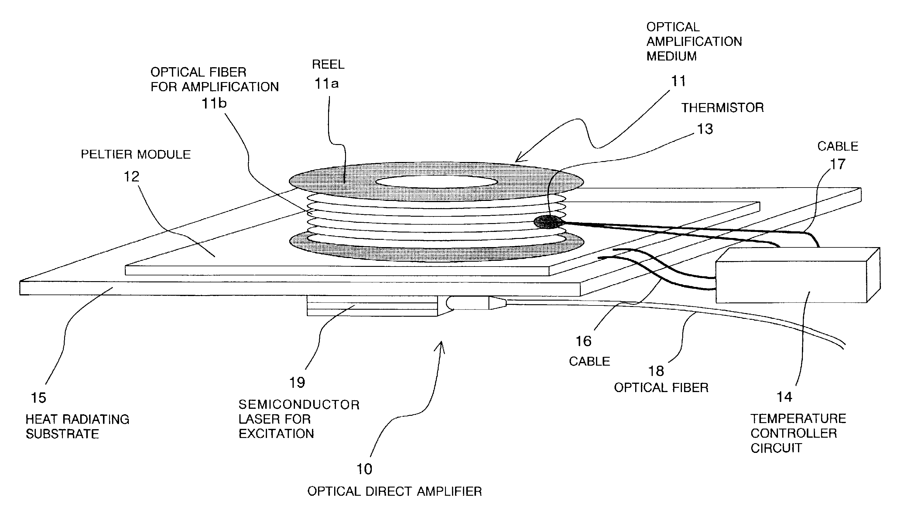
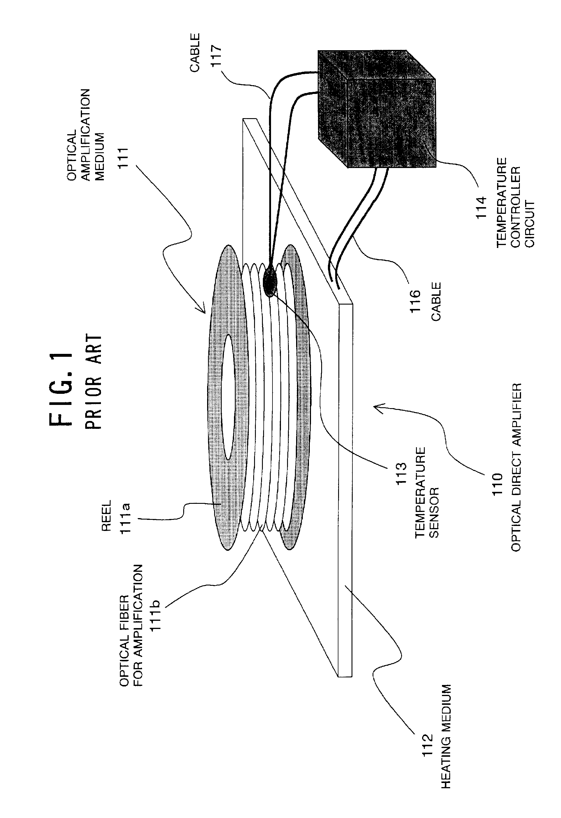
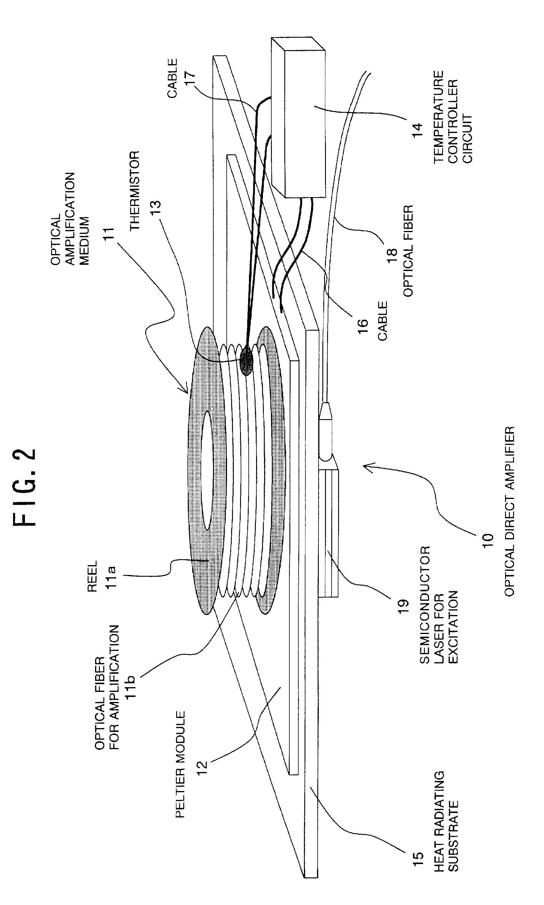
[0046]As shown in FIG. 2, an optical direct amplifier 10 according to a first embodiment comprises an optical amplification medium 11 that carries out an optical amplification function in response to optical excitation by a semiconductor laser 19 for excitation (i.e., an exciting light source), and a temperature controller circuit 14 for controlling the temperature of the amplification medium 11. This point is the same as that of the prior-art optical direct amplifier 110 described previously with reference to FIG. 1.

[0047]However, unlike the prior-art optical direct amplifier 110, the direct amplifier 10 further comprises a heat radiating substrate (i.e., a heat radiating member) 15 for radiating the heat generated by the semiconductor laser 19, and a Peltier module 12 (which is a thermoelectric effect element) for preventing the heat from flowing into the laser 19 from the amplification medium 11, where the Peltier module 12 is provided between the amplification medium 11 and the ...

second embodiment

[0064]An optical direct amplifier 10A according to a second embodiment of the invention has the structure as shown in FIG. 4.

[0065]The structure of the amplifier 10A according to the second embodiment is the same as that of the above-described optical direct amplifier 10 according to the first embodiment except that a heater 20 is additionally mounted on the surface of the reel 11a of the amplification medium 11 opposite to the Peltier module 12. In other words, the structure of the amplifier 10A corresponds to the combination of the structure of the amplifier 10 and the heater 20. Therefore, the explanation about the same structure is omitted here by attaching the same reference numerals as those used in the first embodiment of FIG. 2.

[0066]The heater 20 is an electrical heater that generates heat responsive to the supply of electric power. Here, the shape of the heater 20 is rectangular plate- or sheet-shaped. This shape was determined in consideration of the thermal conductivity ...


PUM


Abstract

An optical direct amplifier lowers the power consumption with a simple structure at a low cost. This amplifier includes an optical amplification medium (e.g., optical fiber) that carries out an optical amplification function in response to optical excitation by an exciting light source (e.g., semiconductor laser); a temperature controller for controlling the temperature of the amplification medium; a heat radiating member for radiating the heat generated by the light source; and a heat transmission regulator (e.g., Peltier module) for allowing the heat to flow into the amplification medium from the light source and for preventing the heat from flowing into the light source from the amplification medium. The amplification medium is heated by application of the heat generated by the light source by way of the heat radiating member and the heat transmission regulator.

Description

[0001]This application is based upon and claims the benefit of priority from Japanese patent application No. 2007-083959 filed on Mar. 28, 2007, the disclosure of which is incorporated herein in its entirety by reference.BACKGROUND OF THE INVENTION[0002]1. Field of the Invention[0003]The present invention relates to an optical direct amplifier and more particularly, to an optical direct amplifier preferably used for Wavelength Division Multiplexing (WDM) optical transmission.[0004]2. Description of the Related Art[0005]In recent years, with the WDM optical transmission system, electric power consumption has been increasing due to the performance enhancement of optical components or devices such as optical cross connects, the speedup in the operation of optical transmitters / receivers for aiming at realization of the transmission of optical signals at 40 Gbit / s, and so on. For this reason, there is an anxiety that power consumption of the individual optical devices used in the WDM opt...

Claims


Application Information

Patent Timeline
Patent Type & Authority Applications(United States)
IPC IPC(8): H01S3/00H01S3/04H01S3/10
CPCH01S3/06704H01S3/06754H01S5/02469H01S3/10007H01S5/02248H01S3/09415H01S3/13017H01S5/02325
Inventor HAMADA, SATOSHI
Owner NEC CORP
Why Eureka
Try Eureka