Method and Apparatus for Electrically Connecting Two Substrates Using a Land Grid Array Connector Provided with a Frame Structure Having Power Distribution Elements

a technology of power distribution elements and land grid arrays, applied in the direction of fixed connections, electrical apparatus construction details, printed circuit structure associations, etc., can solve the problems of increasing the electrical resistance and power dissipation of the power plane, design difficulties and usage limitations, and reducing the electrical resistance of the power plan

Inactive Publication Date: 2008-10-02
IBM CORP
View PDF7 Cites 49 Cited by
  • Summary
  • Abstract
  • Description
  • Claims
  • Application Information

AI Technical Summary

Benefits of technology

[0011]According to the preferred embodiments of the present invention, two substrates are electrically connected using a land grid array (LGA) connector provided with a frame structure having power distribution elements. In one embodiment, the frame structure includes a frame having one or more conductive layers sandwiched between non-conductive layers. The frame may, for example, be a printed wire board (PWB) having power planes that distribute power from a first substrate (e.g., a system PWB) and/or a power cable to a second substrate (e.g., an electronic module). The frame...

Problems solved by technology

However, supplying power or current into the LGA connectors can create design difficulties and usage limitations.
These clearance holes, as discussed in more detail below, can make power distribution difficult in certain portions of the PWB, including the LGA site, because in those portions the planes may resemble something akin t...

Method used


Image

  • Method and Apparatus for Electrically Connecting Two Substrates Using a Land Grid Array Connector Provided with a Frame Structure Having Power Distribution Elements
  • Method and Apparatus for Electrically Connecting Two Substrates Using a Land Grid Array Connector Provided with a Frame Structure Having Power Distribution Elements
  • Method and Apparatus for Electrically Connecting Two Substrates Using a Land Grid Array Connector Provided with a Frame Structure Having Power Distribution Elements

Examples


Embodiment Construction

[0025]1.0 Overview

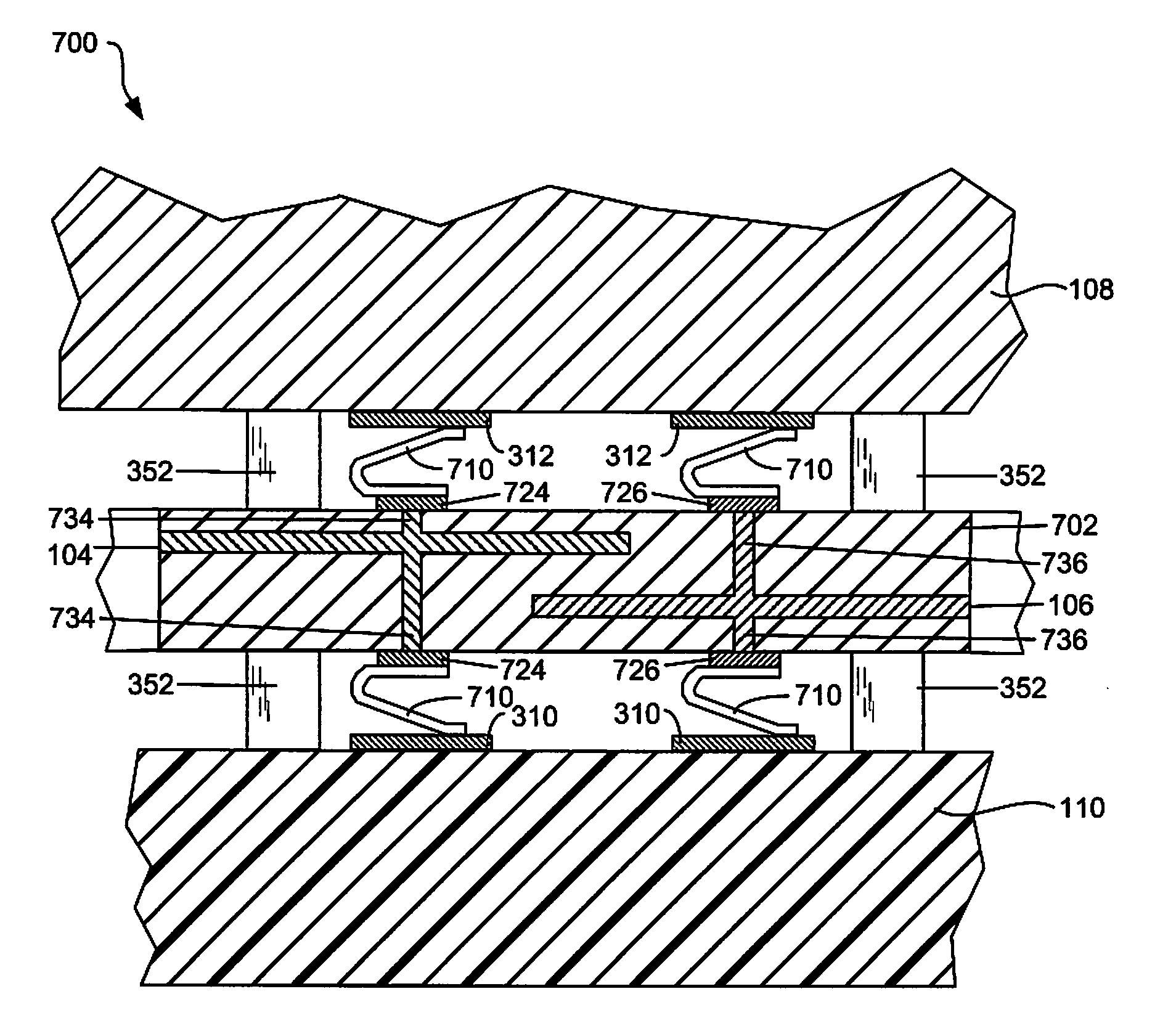
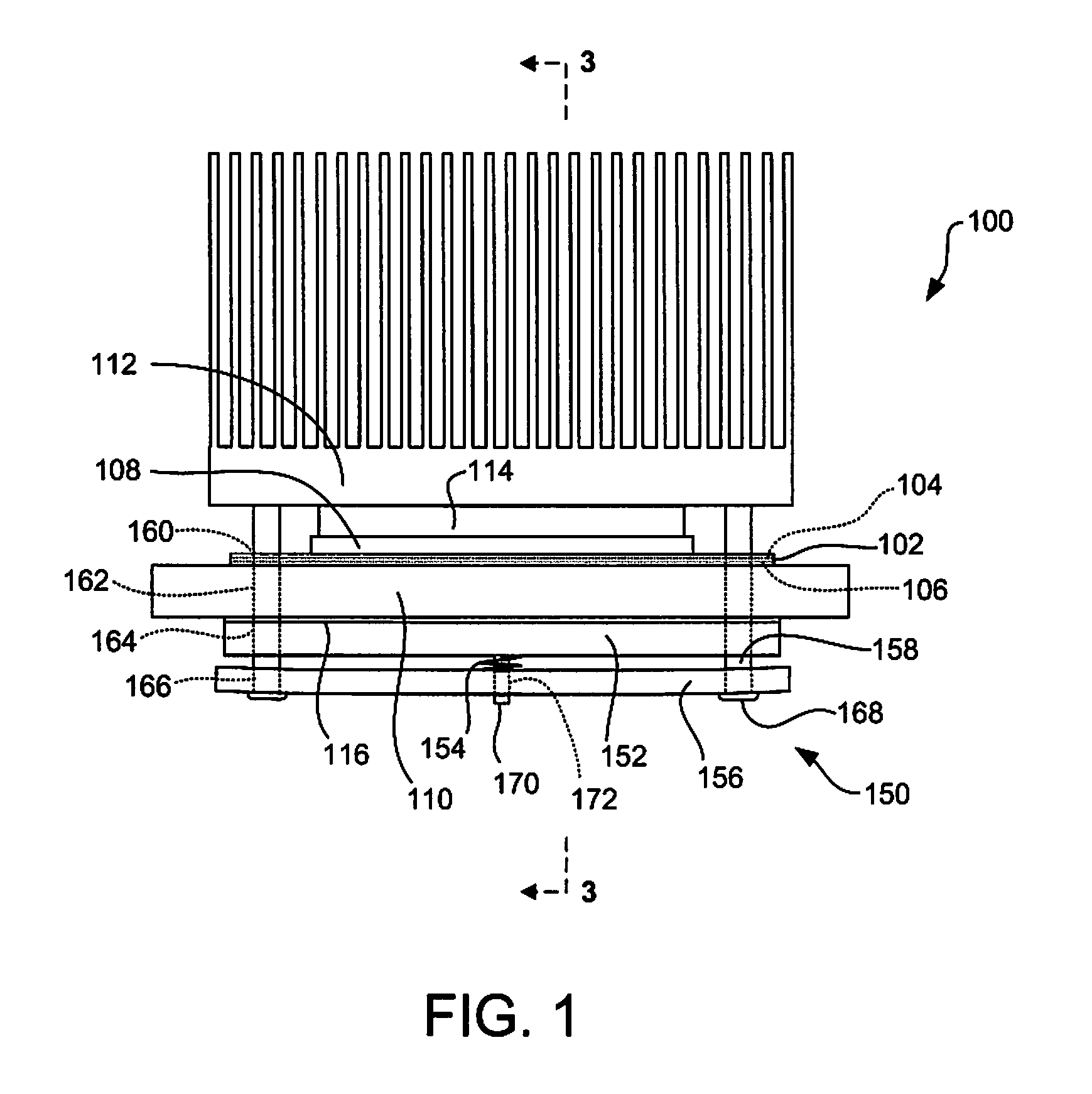
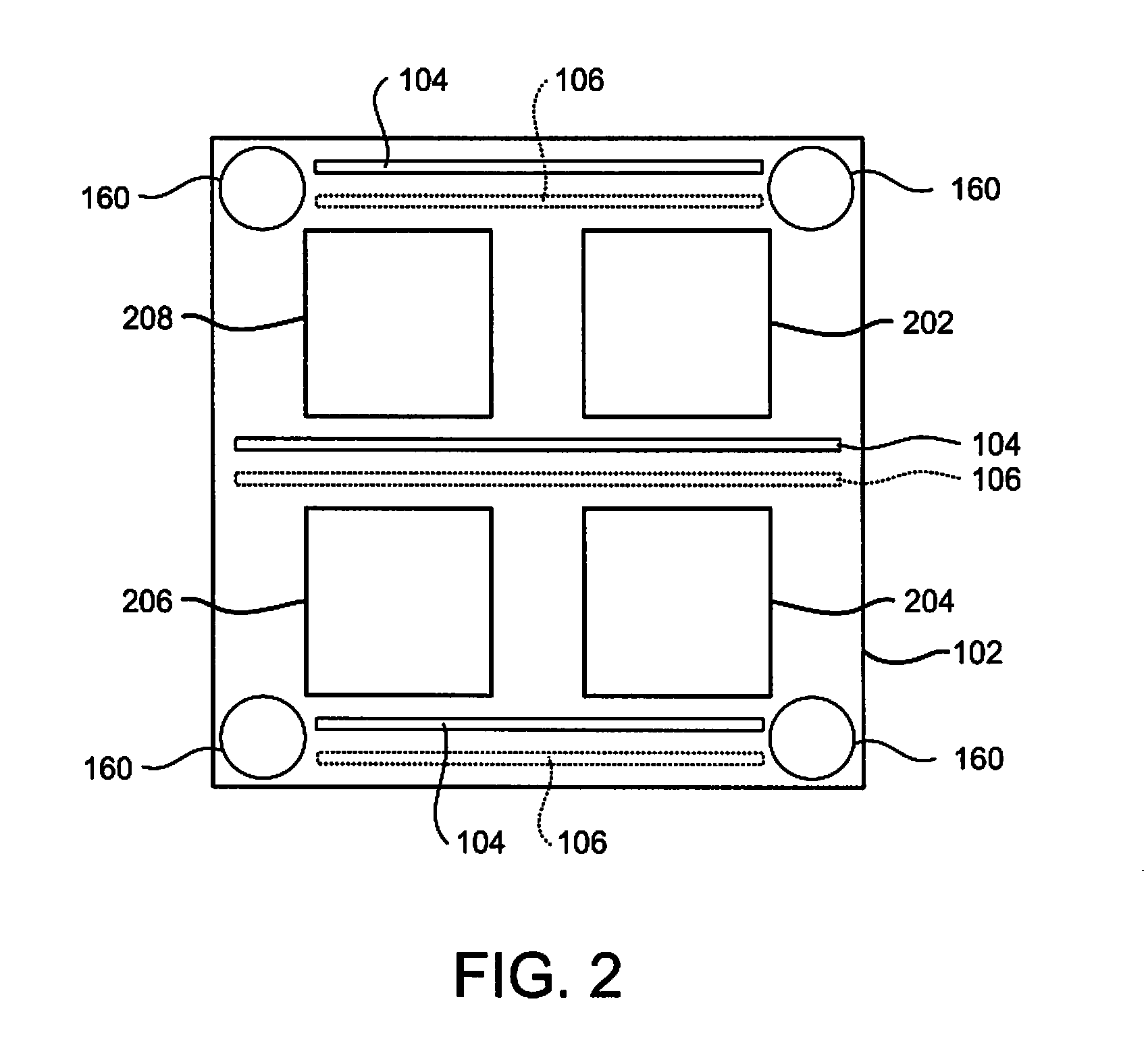
[0026]In accordance with the preferred embodiments of the present invention, two substrates are electrically connected using a land grid array (LGA) connector provided with a frame structure having power distribution elements. In one embodiment, the frame structure includes a frame having one or more conductive layers sandwiched between non-conductive layers. The frame may, for example, be a printed wire board (PWB) having power planes that distribute power from a first substrate (e.g., a system PWB) and / or a power cable to a second substrate (e.g., an electronic module). The frame includes one or more apertures configured to receive an LGA interposer for electrically connecting the two substrates. Preferably, the frame includes four apertures arranged in quadrants that each receive an interposer, and at least one power plane extends between two quadrants and / or adjacent to a peripheral edge of one or more quadrants in the form of stacked and / or parallel bus bars e...


PUM

PropertyMeasurementUnit
Pressureaaaaaaaaaa
Electrical conductivityaaaaaaaaaa
Poweraaaaaaaaaa

Abstract

A method and apparatus for electrically connecting two substrates using a land grid array (LGA) connector provided with a frame structure having power distribution elements. In an embodiment, the frame structure includes a frame having one or more conductive layers sandwiched between non-conductive layers. The frame may, for example, be a printed wire board (PWB) having power planes that distribute power from a first substrate (e.g., a system PWB) and/or a power cable to a second substrate (e.g., an electronic module). The frame includes one or more apertures configured to receive an LGA interposer for electrically connecting the two substrates. Preferably, the frame includes four apertures arranged in quadrants that each receive an interposer, and at least one power plane extends between two quadrants and/or adjacent to a peripheral edge of one or more quadrants in the form of stacked and/or parallel bus bars each defining a power domain.

Description

BACKGROUND OF THE INVENTION[0001]1. Field of Invention[0002]The present invention relates in general to the electrical connector field. More particularly, the present invention relates to land grid array (LGA) connectors incorporating a frame structure having one or more power distribution elements (e.g., bus bars).[0003]2. Background Art[0004]Electrical connectors are in widespread use in the electronics industry. In many computer and other electronic circuit structures, an electronic module such as a central processor unit (CPU), memory module, application-specific integrated circuit (ASIC) or other integrated circuit, must be connected to a printed wiring board (PWB). Printed wiring boards are also known as printed circuit boards (PCBs) and etched wiring boards. When populated with one or more electronic components, a printed wiring board is often referred to as a printed wiring board assembly (PWBA) or a printed circuit board assembly (PCBA). In connecting an electronic module t...

Claims


Application Information

Patent Timeline
IPC IPC(8): H05K7/02
CPCH05K7/1069H01R12/52H01R12/7082Y10T29/49169H01R12/714
Inventor BRODSKY, WILLIAM LOUISHOFFMEYER, MARK KENNETH
Owner IBM CORP
Why Eureka
Try Eureka