
Air-conditioning register assembly and method

a register and air conditioner technology, applied in the field of living space heating and cooling, can solve the problems of insufficient control of the air flow inability to maintain a comfortable environment inability to adjust the temperature of the air in the new living space, so as to achieve the effect of facilitating the flow of conditioned air

Inactive Publication Date: 2008-10-02
MADINA
View PDF46 Cites 18 Cited by
  • Summary
  • Abstract
  • Description
  • Claims
  • Application Information

AI Technical Summary

Benefits of technology

[0005]The invention described herein meets these needs and others, providing an air-conditioning register assembly and method for augmenting the flow of conditioned air from a central air-conditioning unit to a room. Advantageously, the system and method of the invention are independent of the central air-conditioning unit, and therefore do not have to be electrically attached to the central air-conditioning unit to control the fan when the central air-conditioning unit is delivering either heated or cooled air to the room.
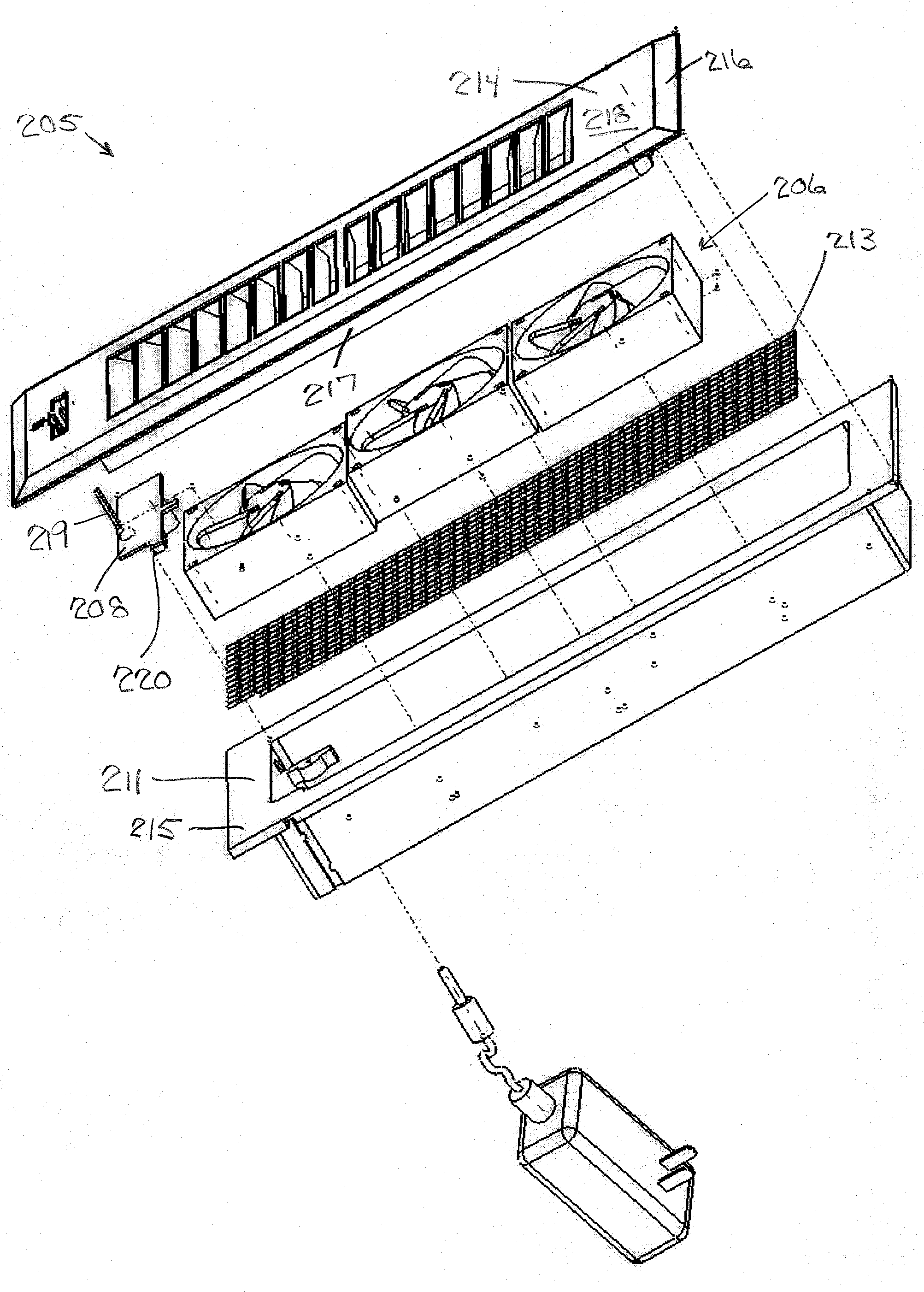
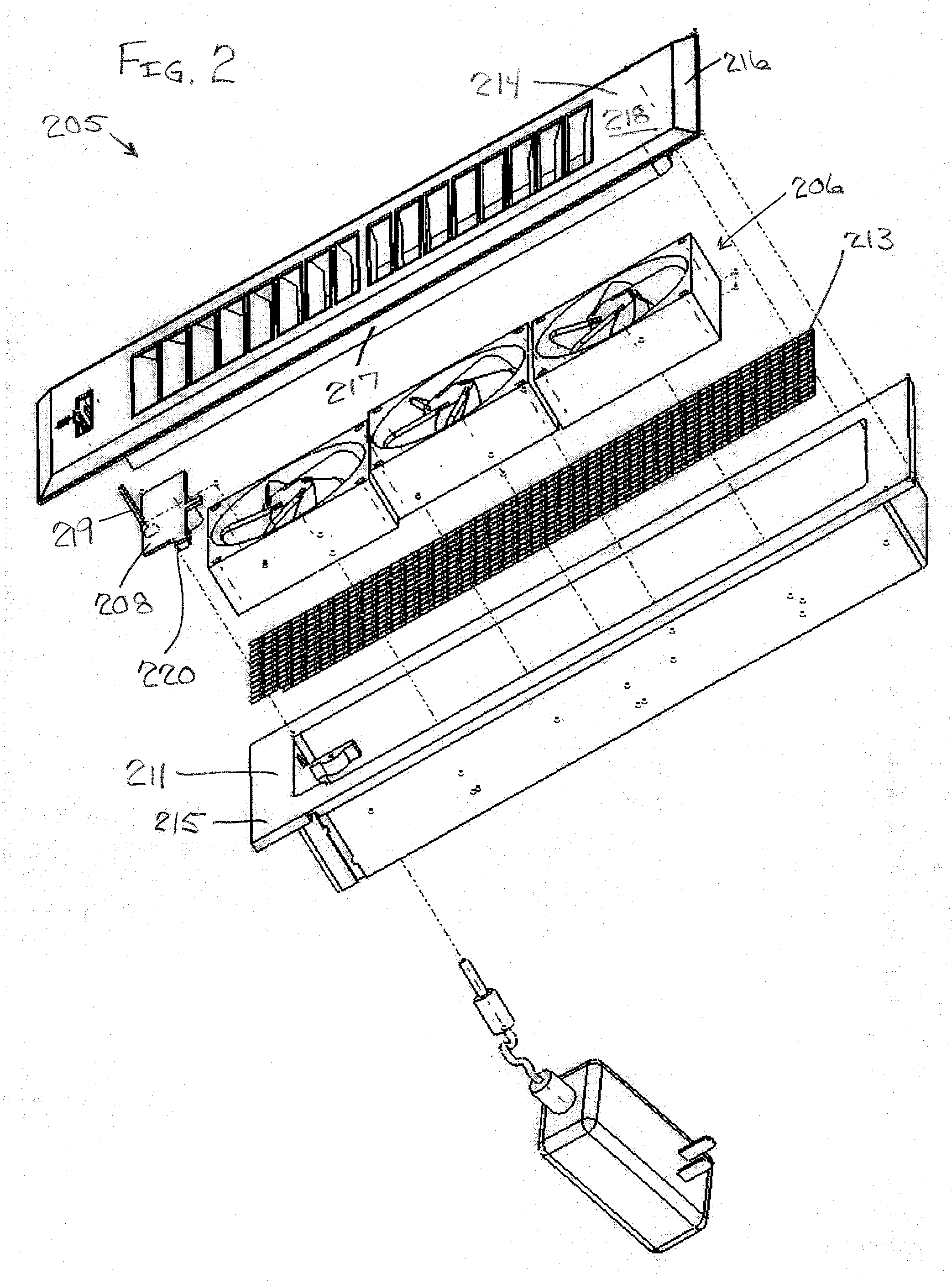
[0010]According to yet another aspect of the invention, the register assembly, further includes a rectangular housing, a screen, and a rectangular shaped top member. The rectangular housing is positioned around the fan, temperature sensor, and processing means, and has side walls, an upper flange extending outward along a top edge of the side walls, and a bottom flange extending inward along a bottom edge of the side walls. The bottom flange supports the fan. The side walls define a rectangular cavity. The screen is sandwiched between the bottom flange and the fan to prevent foreign objects from entering the fan while maximizing air flow. The rectangular shaped top member has a top flange extending outward from a top louvered surface and a rectangular boss extending below the top flange. The top flange mates with the housing upper flange. The rectangular boss mates with housing rectangular cavity.

Problems solved by technology

However, many homes end up with rooms that are not adequately controlled because the conditioned air being delivered through the ducts and vents in the room has an inadequate flow to support the thermal load.
Often, the homeowner or contractor connects the vents in the new living space to existing air-conditioning units within the home, resulting in inadequate flow of air to maintain a comfortable environment in the new living space.
Other times, the home is constructed with very long runs on the supply ducts, again resulting in a “slow vent” within some rooms.
Currently, the home owner has few options when these “slow vents” occur.

Method used


Image

  • Air-conditioning register assembly and method
  • Air-conditioning register assembly and method
  • Air-conditioning register assembly and method

Examples


Embodiment Construction

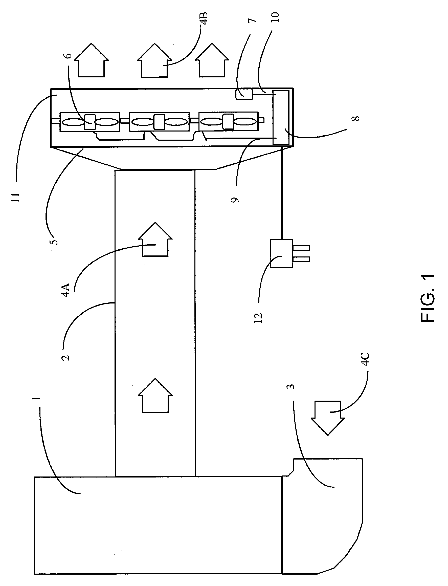
[0026]FIG. 1 is a functional block diagram of an exemplary central air-conditioning system for providing conditioned air to a room. The exemplary central air-conditioning system includes a central air-conditioning unit 1, a delivery duct 2, an air return duct 3, and an exemplary air-conditioning register assembly 5 according to the invention. The air-conditioning unit 1 is a heating and cooling furnace as might be used in a residence or business for climate control. The delivery duct 2 is a an enclosed passage for delivering conditioned (heated or cooled) air 4A from the air-conditioning unit 1 to the register assembly 5 and the room (not shown). The air return duct 3 is an enclosed passage for returning room air 4C to the air-conditioning unit 1 to be heated or cooled. The exemplary air-conditioning register assembly 5 delivers conditioned air 4B to the room.

[0027]The air-conditioning register assembly 5 is comprised of fans 6, a temperature sensor 7, a processing means 8, an housi...


PUM


Abstract

A register assembly for augmenting the flow of conditioned air from a central air-conditioning unit to a room includes a fan, a temperature sensor, and a processing means. The fan is operably positioned for increasing air flow through the register assembly. The temperature sensor is for measuring a temperature of air in the register assembly and for outputting a measured temperature signal. The processing means is for: receiving the measured temperature signal; using the measured temperature signal in determining whether the central air-conditioning unit is providing conditioned air to the room; and activating the fan to augment the conditioned air flow if the central air-conditioning unit is providing conditioned air to the room. The processing means also provides drift compensation to prevent unwanted operation of the fan due to temperature drifts. The register assembly may include a rectangular housing positioned around the components for use in a floor vent, or a housing adapting a floor vent to a centrifugal, tower fan.

Description

BACKGROUND OF THE INVENTION[0001]1. Field of the Invention[0002]The present invention relates to the heating and cooling of living spaces. More particularly, this invention relates to an air-conditioning register assembly and method for augmenting the flow of conditioned air from a central air-conditioning unit to a room.[0003]2. Description of Prior Art[0004]Modern homes use central air-conditioning units to provide conditioned (heated or cooled) air for environmental control through a system of ducts and vents into the rooms of the homes. However, many homes end up with rooms that are not adequately controlled because the conditioned air being delivered through the ducts and vents in the room has an inadequate flow to support the thermal load. These “slow vents” often result from expansion of the living space, like a basement, garage, or attic or other unfinished area being converted into standard living space by the installation of insulation, sheetrock, carpet, and other materia...

Claims


Application Information

Patent Timeline
Patent Type & Authority Applications(United States)
IPC IPC(8): F24F7/06F24F7/00F24F13/06
CPCF24F7/06F24F11/0012F24F11/053F24F13/06F24F2001/0062F24F1/0033F24F11/30F24F2110/10F24F11/76F24F1/00075F24F11/52F24F11/61F24F11/63
Inventor EL-GALLEY, RIZKCAMPBELL, RICHARD A.MCGINTY, JOSEPH R.
Owner MADINA
Learn More