Ventilation system

Inactive Publication Date: 2008-10-02
MATSUSHITA ELECTRIC WORKS LTD
View PDF4 Cites 29 Cited by
  • Summary
  • Abstract
  • Description
  • Claims
  • Application Information

AI Technical Summary

Benefits of technology

[0006]It is an object of the present invention to provide a ventilation system capable of widely spraying mist o

Problems solved by technology

However, in case of the air cleaner, one or more air cleaners are required in addition to the ventilation system, and accordingly living spaces are reduced.
However, since the atomizer is located at an intermed

Method used


Image

  • Ventilation system
  • Ventilation system
  • Ventilation system

Examples


first embodiment

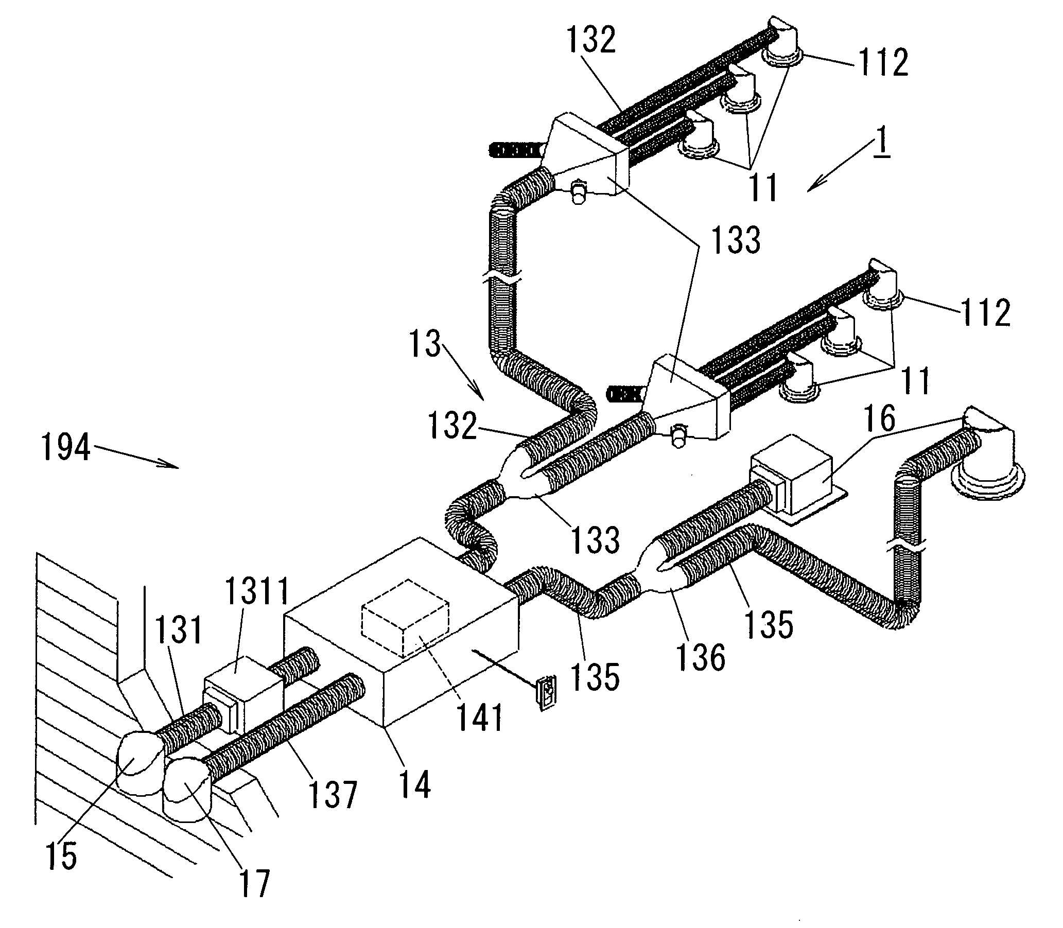
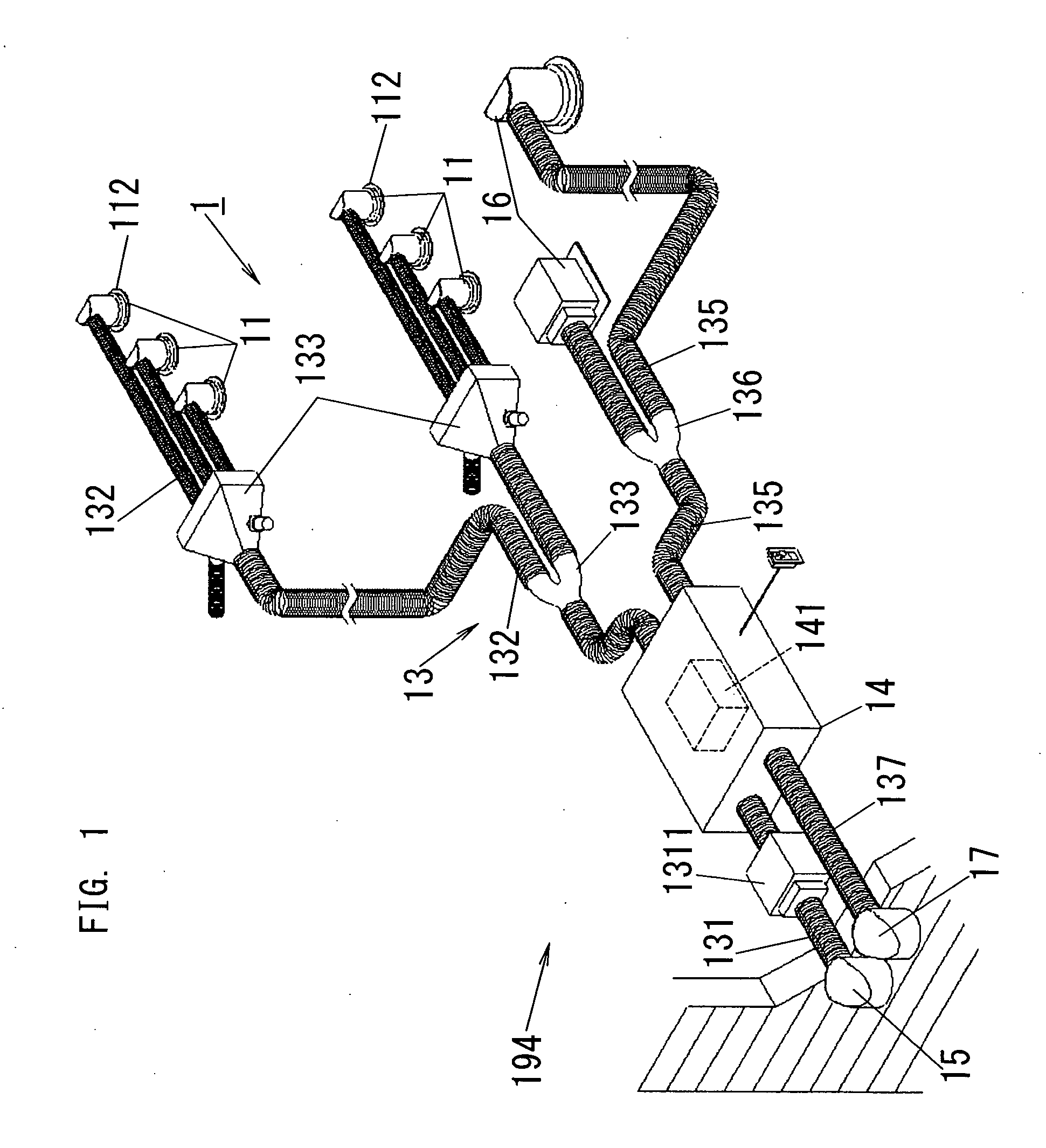
[0050]FIG. 1 shows a schematic diagram of a ventilation system 1, in accordance with a first embodiment of the present invention. The ventilation system 1 is a residential ventilation system.

[0051]This system includes ductwork 13; a fan (ventilation fan) 141 for creating a current of air passing through the ductwork 13; and air supply outlets 112 for supplying outdoor air into each living space (see living space (room) 191 of FIG. 2) of a house by means of the current of air.

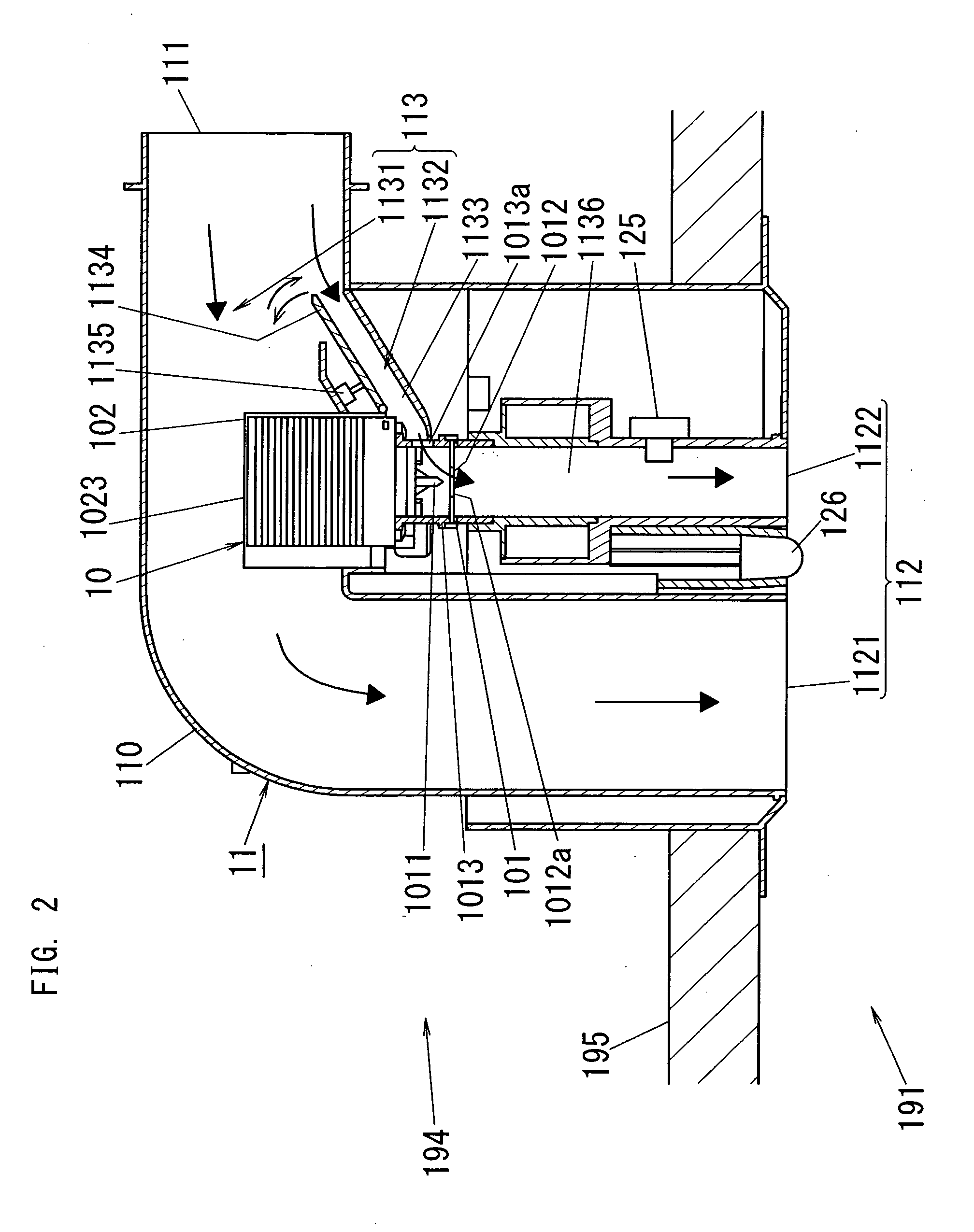
[0052]Specifically, the ventilation system 1 includes: the ductwork 13; a heat exchanger 14 having the fan 141; an exterior supply grille 15; interior exhaust grilles 16; an exterior exhaust grille 17; and interior supply grilles 11 each of which has the air supply outlet 112. The exterior supply grille 15 and the exterior exhaust grille 17 are located outside the house, and the interior exhaust grilles 16 and the interior supply grilles 11 are located at the openings of the ceilings in the house.

[0053]As shown ...

second embodiment

[0068]FIGS. 6-8 and 9A-9D show schematic diagrams of an interior supply grille 21 of a ventilation system, in accordance with a second embodiment of the present invention. This ventilation system is formed in the same way as the first embodiment except the interior supply grille 21.

[0069]The interior supply grille 21 includes a body case 210 having an air supply inlet 211, the air supply outlet 212 and a passage 213 connected between the inlet 211 and the outlet 212. The air supply inlet 211 is connected with the supply ductwork of the ventilation system. The air supply outlet 212 is located at an opening 296 of a ceiling 295 of a living space 291, and also connected with the supply ductwork through the passage 213. The passage 213 can be divided into supply and bypass passages 2131 and 2132 through which outdoor air from the supply ductwork passes. The supply passage 2131 is formed of an L-shaped supply pipe, and the base end of this supply pipe sticks out from the side of the body...

third embodiment

[0087]FIG. 13 shows a schematic diagram of a ventilation system 3, in accordance with a third embodiment of the present invention. In the same way as the first embodiment, the ventilation system 3 includes ductwork 33, a heat exchanger 34 having a fan (ventilation fan), an exterior supply grille 35, interior exhaust grilles 36 and an exterior exhaust grille 37. The ductwork 33 has: supply ductwork formed of an upstream supply duct 331 (having a filter 3311), downstream supply ducts 332 and distributors 333; and exhaust ductwork formed of an upstream exhaust duct(s) 335, and a downstream exhaust duct 337. In case that a plurality of upstream exhaust ducts 335 are used, a distributor(s) for the ducts 335 is further added.

[0088]As shown in FIGS. 13 and 14, the ventilation system 3 is characterized by interior supply grilles 31 each of which has an air supply outlet 312. At least one interior supply grille 31 is installed on a ceiling 395 of each living space 391 having its own partitio...


PUM


Abstract

A ventilation system comprises ductwork, a fan for creating a current of air passing through the ductwork, and an air supply outlet for supplying outdoor air into a living space of a house by means of the current of air. The ventilation system further comprises an electrostatic atomizer located at the side of the air supply outlet. The electrostatic atomizer is configured to produce mist of charged fine water particles by means of electrostatic atomization to spray the mist into the living space.

Description

TECHNICAL FIELD[0001]The invention relates generally to ventilation systems and more particularly to a residential ventilation system.BACKGROUND ART[0002]Many houses have been tight and well insulated in recent years, and accordingly ventilation systems are required to be installed in the houses in order to expel pollutants generated in the houses, such as carbon monoxide, carbon dioxide, volatile organic compounds etc. In a prior art ventilation system, outdoor air is supplied into a house through ductwork located in a ceiling crawl space, while indoor air is expelled through the ductwork at the same time. The ventilation fan in the ductwork is driven so that ventilation is performed for 24 hours. In another prior art ventilation system, indoor air is expelled through an exhaust fan, while outdoor air is supplied into a house through vents installed in exterior walls at the same time. Also in this case, ventilation is performed for 24 hours by driving the exhaust fan.[0003]Japanese...

Claims


Application Information

Patent Timeline
IPC IPC(8): F24F7/06F24F1/0059
CPCF24F6/14F24F12/006Y02B30/563F24F2012/007Y02B30/545F24F2001/0088F24F1/0007Y02B30/54Y02B30/56F24F1/0059
Inventor ASANO, YUKIYASUONO, HISAHITOISAKA, ATSUSHIMURASE, SHINYATOYOMI, YURITSUGU
Owner MATSUSHITA ELECTRIC WORKS LTD
Why Eureka
Try Eureka