Eddy current reducing device for magnetic resonant imaging equipment

A magnetic resonance imaging and eddy current technology, which is applied in magnetic resonance measurement, measuring devices, and measuring magnetic variables, etc., can solve the problems of magnetic permeability saturation, shortening pulse rise time, increasing the time for gradient pulse to reach the predetermined magnetic field strength, etc. , to achieve high saturation magnetic flux density, improve imaging clarity, and accelerate rise time

Inactive Publication Date: 2004-07-28
WUHAN INST OF PHYSICS & MATHEMATICS CHINESE ACADEMY OF SCI
View PDF1 Cites 0 Cited by
  • Summary
  • Abstract
  • Description
  • Claims
  • Application Information

AI Technical Summary

Problems solved by technology

The eddy current in turn affects the shape of the rectangular wave of the magnetic field generated by the gradient coil, increases the time for the gradient pulse to reach the predetermined magnetic field strength, and prevents the gradient magnetic field strength between two adjacent gradient pulses from returning to zero, directly affecting the imaging quality. Positioning accuracy affects the clarity of MRI imaging
[0003] In order to solve the above problems, it is necessary to try to reduce the conductivity of the pole shoe material. In the US Patent No. 4827235, a non-conductive material, that is, an amorphous metal mixture or composite material is used to make the pole shoe. Although this method shortens the pulse rise Time, its disadvantage is that the material is expensive, and under the condition of strong magnetic field, the magnetic permeability of the material will be saturated and reduced, which greatly hinders its application in high field strength MRI devices
The Japanese Patent Publication No. CN1116312A uses silicon steel sheets to face the lamination in the direction of space. The disadvantage is that since the ferrosilicon sheet has a large coercive force, the matrix formed by it has a certain area, which is very important for preventing the residual magnetism from destroying the uniformity of the spatial magnetic field. The effect is not significant enough

Method used


Image

  • Eddy current reducing device for magnetic resonant imaging equipment
  • Eddy current reducing device for magnetic resonant imaging equipment
  • Eddy current reducing device for magnetic resonant imaging equipment

Examples


Embodiment Construction

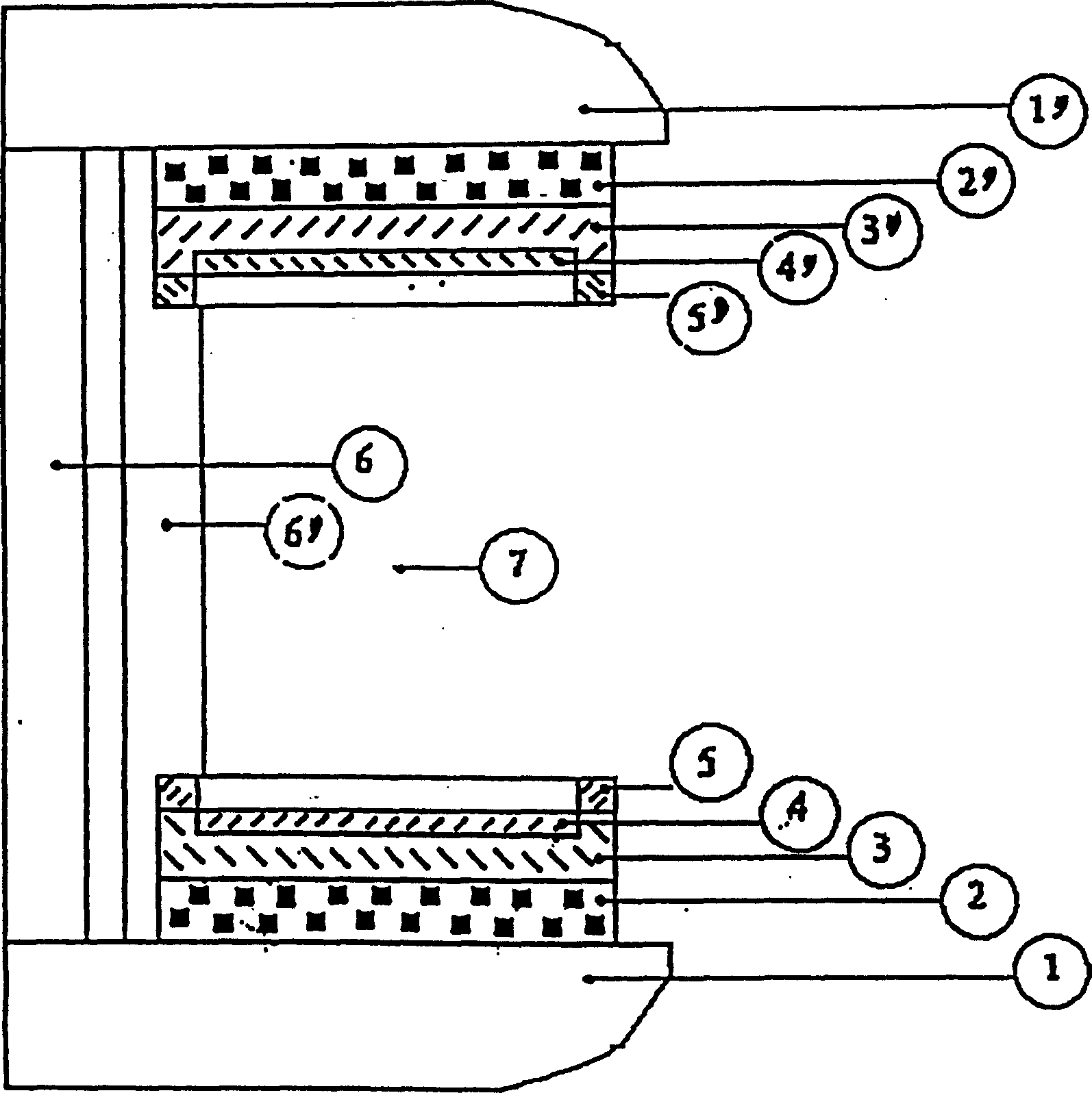
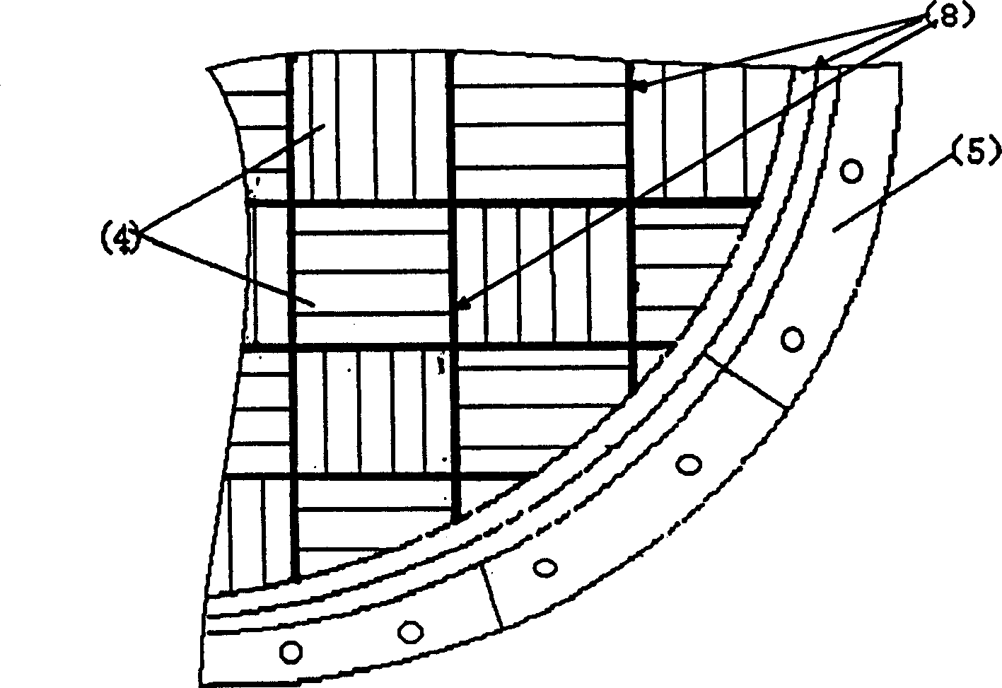
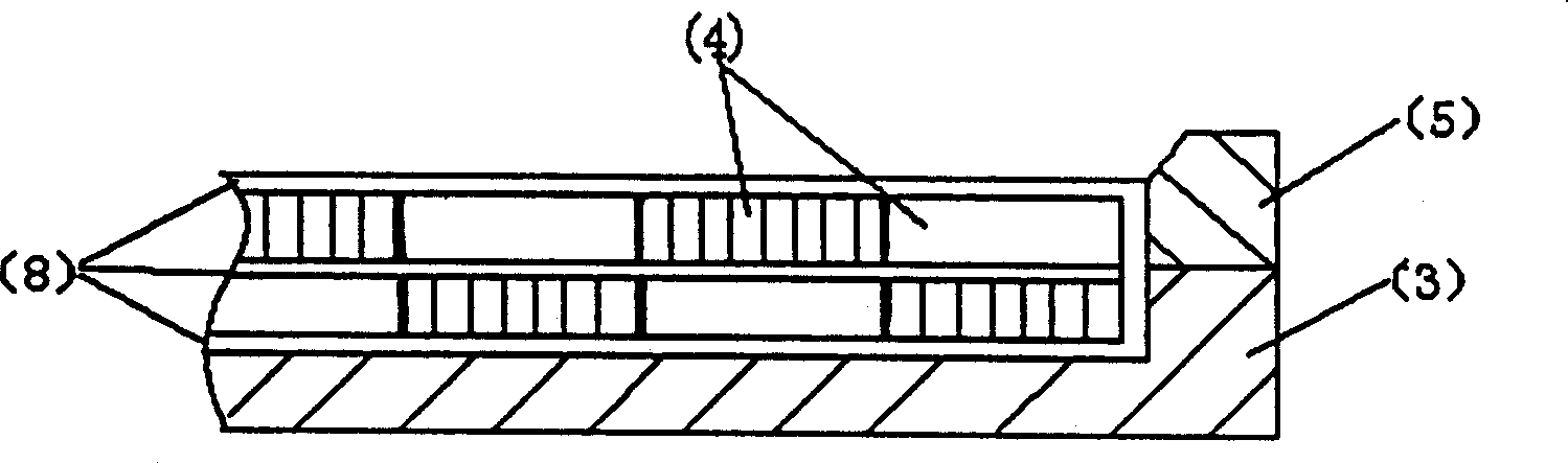
[0019] The eddy current reducing device of the present invention first sticks insulating material on the pole shoe with epoxy resin or anaerobic adhesive, and the insulating material can be resin, film or hardwood, and then the thickness is 0.2-0.5 mm, and the shape is 5-14 mm × 60-60 mm. 100 mm rectangular non-oriented ferrosilicon sheet impregnated with resin paint, use epoxy resin or anaerobic adhesive to bond the resin-impregnated ferrosilicon sheet into a square laminate, and laminate the laminate with epoxy resin or anaerobic adhesive Connected to the insulating material on the pole shoe, the ferrosilicon sheets in the laminations are arranged along the direction of the static magnetic field of the permanent magnet, and the arrangement directions of the ferrosilicon sheets between the laminations are perpendicular to each other, and the ferrosilicon sheets are made of resin, film, and hardwood. Insulate each other, process the lamination bonded on the insulating material ...


PUM


Abstract

The vortex-reducing device in the magnetic resonance imaging equipment is characterized by that: soaking the orientationless silicon iron sheets in resin paint, then sticking them into square laminated body, sticking the laminated body on the pole shoe, using insulating material to retain insulation between the laminated bodies, between laminated body and pole shoe and between the laminated body and uniform field ring, making the laminated body into the form similar to pole shoe, and sticking second layer of insulating material and laminated body on first layer of laminated body, two layers of laminated bodies are pperpendicular and more sticking insulating material on the second layer of laminated body. Said invention can raise dimage resolution of said imaging equipment.

Description

Technical field: [0001] The present invention relates to a magnetic resonance imaging (hereinafter referred to as MRI) device, and more particularly to an MRI eddy current reducing device. The eddy current reducing device protects the uniformity of the magnetic field of the magnetic resonance imaging device, so as to improve the imaging definition of the MRI device. Background technique: [0002] The basic requirement of a magnetic resonance imaging (MRI) device is to superimpose a rapidly changing gradient magnetic field on a uniform static magnetic field, and give the nuclear magnetic resonance signal corresponding to the position information in the imaging body, and obtain it through a series of precise pulsed gradient magnetic fields. image. In general, the two yoke irons of the permanent magnet of the magnetic resonance imaging device are connected by two columns to form an open detection area. The magnetic steel is made of NdFeB magnetic material, which is fixed on th...

Claims


Application Information

Patent Timeline
Patent Type & Authority Patents(China)
IPC IPC(8): G01R33/38G01R33/3873
Inventor 邱衍军肖圣前曾凡明
Owner WUHAN INST OF PHYSICS & MATHEMATICS CHINESE ACADEMY OF SCI
Why Eureka
Try Eureka