
Nickel zinc ferrite magnetic shielding inductor product and manufacturing method thereof

A nickel-zinc ferrite and inductor technology, used in the manufacture of inductors/transformers/magnets, circuits, electrical components, etc., can solve the problems of low saturation magnetic flux density and poor temperature characteristics, and improve the resistance to DC superposition. The ability to improve the anti-interference ability, the effect of reducing the size

Inactive Publication Date: 2013-03-27
DANFENG RONGYI ELECTRONICS
View PDF6 Cites 7 Cited by
  • Summary
  • Abstract
  • Description
  • Claims
  • Application Information

AI Technical Summary

Problems solved by technology

However, the material still has problems such as poor temperature characteristics and low saturation magnetic flux density in practical applications.

Method used


Image

  • Nickel zinc ferrite magnetic shielding inductor product and manufacturing method thereof
  • Nickel zinc ferrite magnetic shielding inductor product and manufacturing method thereof
  • Nickel zinc ferrite magnetic shielding inductor product and manufacturing method thereof

Examples


Embodiment 1

[0027] Fe as the main component of the present invention 2 o 3 , NiO, ZnO, CuO according to the ratio set in the table below,

[0028] material name

[0029] Vibrate and mix the prepared main component raw materials with a vibrating ball mill for 15 minutes, and then pre-calcine their mixture in the air for 3 hours. The pre-burned material is mixed and pulverized with a ball mill (12 hours). During the pulverization process, the ratio of the material to water is 1: 2 by weight; after the pulverization is completed, it is dried, and the concentration is 10% polyvinyl alcohol is added during drying. Solution, the addition ratio is calculated as 11% of the total material weight according to the polyvinyl alcohol solution; after adding polyvinyl alcohol, it is made into a powder, and the full-automatic rotary press is used at 2t / cm 2 Under the pressure of high pressure, the powder is pressed into a rod-shaped magnetic core and a square cap-shaped magnetic core blank wi...

Embodiment 2

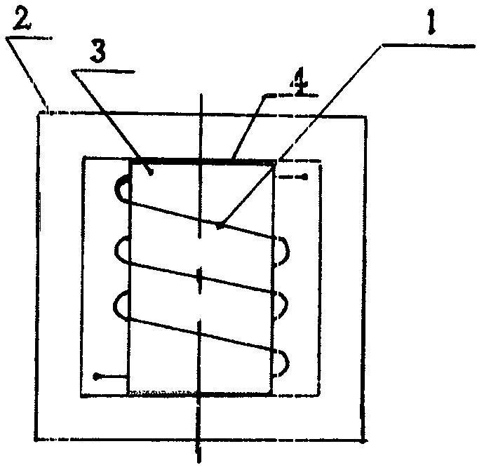
[0031] With the nickel-zinc ferrite material obtained by the present invention at 2t / cm 2 The cap-shaped magnetic core and the rod-shaped magnetic core blank are respectively formed under pressure. The shapes of these two kinds of magnetic core blanks are shown in the appendix figure 1 , sintering the obtained blank in air at 1160° C. for 3 hours to obtain a rod-shaped magnetic core 3 and a cap-shaped magnetic core 2 .

[0032] as attached figure 1 As shown, use a winding machine to wind the Φ0.8mm enameled wire into an air-core coil 1 with an inner diameter of 3mm, and the number of winding turns is 5 turns. The coil 1 is fixed on the rod-shaped magnetic core 3 with an adhesive 4 to ensure that the coil is stable. The position is in the center of the rod-shaped magnetic core; the rod-shaped magnetic core 3 with the coil 1 is fixed in the cap-shaped magnetic core 2 with an adhesive to obtain a magnetically shielded inductor.


PUM


Abstract

The invention relates to a nickel zinc ferrite magnetic shielding inductor product and a manufacturing method thereof. A raw material for manufacturing a magnetic shielding inductor mainly comprises ferric oxide, nickel oxide, zinc oxide and copper oxide, and an auxiliary component of the raw material comprises bismuth trioxide, molybdenum trioxide or vanadium pentoxide. The manufacturing method of the magnetic shielding inductor includes that the materials the mixed, sintered and made into powder materials, the powder materials are pressed into a rodlike magnetic core and a square cap-shaped magnetic core blank, the square cap-shaped magnetic core blank is placed in an air kiln to be sintered, the rodlike magnetic core is installed in a sintered square cap-shaped magnetic core after a solenoid coil is installed on the rodlike magnetic core, and the magnetic shielding inductor is manufactured. A special inductor structure and an assembly method are adopted so as to enable the inductor to shield external electromagnetic fields, and anti-interference capacity of the conductor can be improved. Nickel zinc ferrite materials with high saturation magnetic flux density are adopted, tolerance of direct current superposition of the inductor can be improved, and requirements of the inductor for miniaturization, thinning, high frequency, high performance and the like are met.

Description

technical field [0001] The invention belongs to the technical field of magnetic material products, and relates to a magnetic shielding inductor product made of nickel-zinc ferrite material and a manufacturing method of the inductor. Background technique [0002] With the development of CPU, FPGA and different types of chip ASIC (application specific integrated circuit) technology products, low voltage and high current are becoming the development trend of DC-DC power supply. At present, replacing 5V with 3.3V has become the most common DC power supply voltage, and the power supply voltage adopts 2.5V, 1.8V, 1.5V, 1.2V or even lower than 1V, and the current reaches 40A, 60A, 80A, 100A, 160A or even higher The DC-DC power supply is gradually becoming the mainstream of market products. As a circuit technology for obtaining such a large current, several DC-DC converters are now commonly used to form a polyphase power supply circuit instead of only one DC-DC converter power supp...

Claims


Application Information

Patent Timeline
Patent Type & Authority Applications(China)
IPC IPC(8): H01F1/34H01F41/00H01F41/02C04B35/26
Inventor 徐保田李蕾陈元星
Owner DANFENG RONGYI ELECTRONICS
Learn More