
Magnetic material for light emitting diode (LED) illumination control circuit

A technology of LED lighting and magnetic materials, applied in the direction of magnetic materials, circuits, magnetic objects, etc., can solve the problems of LED driving power supply reducing power supply volume, high circuit operating frequency, low initial magnetic permeability, etc., to achieve low power consumption, Effects of high frequency power consumption and high initial permeability

Active Publication Date: 2011-08-24
SHANDONG ZHONGRUI ELECTRONICS
View PDF5 Cites 8 Cited by
  • Summary
  • Abstract
  • Description
  • Claims
  • Application Information

AI Technical Summary

Problems solved by technology

But because NiO is used in this invention, NiO is a relatively expensive material, so its manufacturing cost is high
[0010] However, due to the above materials, although the saturation flux density is high at 100°C, the initial permeability is still relatively high due to the high power consumption of the core. Low, thus affecting the use of this ferrite material in more occasions, to be precise, it cannot be applied to small-sized, high-power LED drive power supplies (in order to reduce the size of the power supply, the circuit operating frequency is higher, and to transmit larger Power, choke coils and transformers work in a state of high magnetic flux density, and at the same time there is a large current passing through the choke coil)

Method used


Image

  • Magnetic material for light emitting diode (LED) illumination control circuit

Examples


Embodiment 1

[0039] Embodiment 1: formula (mol ratio) by main component: Fe 2 o 3 : 59.8mol%, ZnO: 10.8mol%, MnO: 31mol%, weigh Fe 2 o 3 , Mn 3 o 4 and ZnO. Put it into a sand mill pre-added with deionized water for grinding, the water content of the slurry is 40%, and the sanding time is 0.5 hours. After the slurry is sprayed and granulated once, it is pre-fired with an electric-heated rotary kiln at 850 degrees. Then the calcined material is put into a sand mill with deionized water in advance for secondary sand grinding, the water content of the slurry is 30%, and KCO is added relative to the main component content in the sand grinding process 3 : 0.03wt%, Y 2 o 3 : 0.05wt%, CaO: 0.08wt%, SiO 2 : 0.015wt%, in addition, also added MgO: 0.1wt%, V 2 o 5: 0.035wt%, CoO: 0.25wt%, the sanding time is 1.5 hours, and the average grain size of sanding is controlled to be 1.1±0.3 μm. Finally, secondary spraying is carried out to obtain MnZn ferrite particle powder. Take the pellets an...

Embodiment 2

[0042] Embodiment 2: formula (mol ratio) by main component: Fe 2 o 3 : 60.5mol%, ZnO: 10.5mol%, MnO: 29.0mol%, weigh Fe 2 o 3 , Mn 3 o 4 and ZnO. Put it into a sand mill pre-added with deionized water for grinding, the water content of the slurry is 40%, and the sanding time is 0.5 hours. After the slurry is sprayed and granulated once, it is pre-fired with an electric heating rotary kiln at 880 degrees. Then the calcined material is put into a sand mill with deionized water in advance for secondary sand grinding, the water content of the slurry is 30%, and KCO is added relative to the main component content in the sand grinding process 3 : 0.12wt%, Y 2 o 3 : 0.03wt%, CaO: 0.10wt%, SiO 2 : 0.01wt%, in addition, Nb is also added 2 o 5 : 0.03wt%, ZrO 2 : 0.02wt%, CoO: 0.25wt%, in addition, also added, the sanding time was 1.5 hours, and the average particle size of the sanding was controlled to be 1.1±0.3 μm. Finally, secondary spraying is carried out to obtain MnZn ...

Embodiment 3

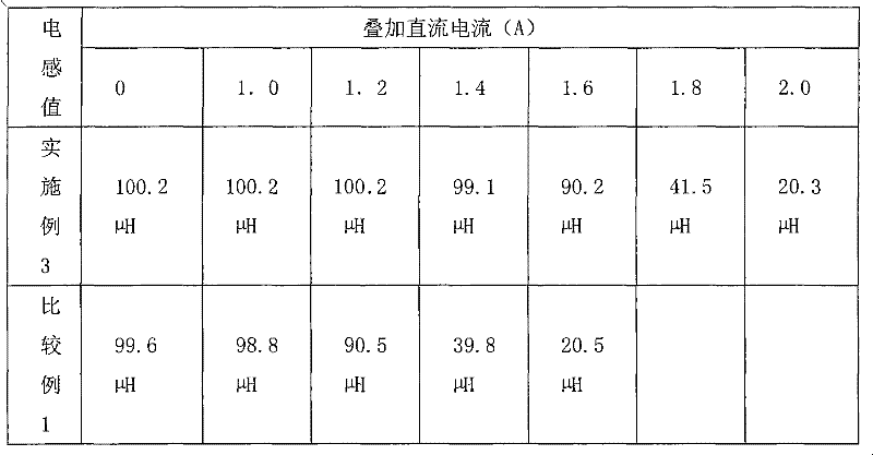
[0045] Embodiment 3: formula (mol ratio) by main component: Fe 2 o 3 : 61.5mol%, ZnO: 11.5mol%, MnO: 27.0mol%, weigh Fe 2 o 3 , Mn 3 o 4 and ZnO. Put it into a sand mill pre-added with deionized water for grinding, the water content of the slurry is 40%, and the sanding time is 0.5 hours. After the slurry is sprayed and granulated once, it is pre-fired with an electric heating rotary kiln at 900 degrees. Then the calcined material is put into a sand mill with deionized water in advance for secondary sand grinding, the water content of the slurry is 30%, and KCO is added relative to the main component content in the sand grinding process 3 : 0.04wt%, Y 2 o 3 : 0.10wt%, CaO: 0.15wt%, SiO 2 : 0.035wt%, in addition, also added MgO: 0.30wt%, V 2 o 5 : 0.05wt%, ZrO 2 : 0.04wt%, the sanding time is 1.5 hours, and the average grain size of the controlled sanding is 1.1±0.3 μm. Finally, secondary spraying is carried out to obtain MnZn ferrite particle powder. Take the pell...


PUM

PropertyMeasurementUnit
particle sizeaaaaaaaaaa
densityaaaaaaaaaa
saturation flux densityaaaaaaaaaa

Abstract

The invention discloses a magnetic material for a light emitting diode (LED) illumination control circuit, and is characterized in that: the magnetic material is MnZn ferrite, which comprises the following main components: 59.5 to 61.8 mol percent of Fe2O3, 9 to 12 mol percent of ZnO and the balance of MnO, and following auxiliary components (based on the total content of the main components): 0.01 to 0.15 weight percent of KCO3, 0.008 to 0.10 weight percent of Y2O3, 0.01 to 0.25 weight percent of CaO, 0.005 to 0.055 weight percent of SiO2, 0.005 to 0.50 weight percent of MgO, 0.005 to 0.06 weight percent of V2O5, 0.01 to 0.50 weight percent of CoO, 0.005 to 0.08 weight percent of Nb2O5 and 0.005 to 0.055 weight percent of ZrO2. The magnetic material is characterized in that: the magneticconductivity at the temperature of 25 DEG C is 1,500+ / -25 percent; the saturated magnetic flux density at the temperature of 100 DEG C is more than 500mT; and the power consumption at the temperatureof 100 DEG C and 100KHz*200mT is less than 620mW / cm<3>.

Description

technical field [0001] The invention relates to a magnetic material for an LED lighting control circuit and a preparation method thereof. Background technique [0002] LED lighting needs to work under DC conditions, so a driving power supply is required, and in the design of various control circuits (also known as driving circuits), choke coils are usually used, which are magnetic cores made of magnetic materials and Composed of coils wrapped around it. The choke coil is a key component of the drive circuit, and its performance directly determines whether the LED lighting can work normally. [0003] As the choke coil of the drive circuit, its working circuit often contains both AC and DC components. Sometimes the LED drive power supply is installed in the lamp, and its ambient operating temperature is relatively high, sometimes reaching 100°C or even higher. In order to ensure that the LED can work normally, it is required that the choke coil of the driving circuit should ...

Claims


Application Information

Patent Timeline
Patent Type & Authority Applications(China)
IPC IPC(8): H01F1/36C04B35/26C04B35/64
CPCC04B2235/3206C04B2235/5481C04B35/6262C04B2235/6584C04B2235/3225C04B2235/6562C04B2235/3201C04B2235/3251C04B2235/664C04B2235/72C04B2235/3418C04B2235/3275C04B2235/5436C04B2235/3208H01F1/36C04B35/62695H01F1/344C04B2235/3239C04B35/62685C04B35/6263C04B2235/3262C04B2235/6565C04B2235/3284C04B35/2658C04B2235/3244C04B2235/604C04B2235/3263
Inventor 陆明岳
Owner SHANDONG ZHONGRUI ELECTRONICS
Learn More